Infiniti M35/M45 Y50. Manual - part 783


  Index      Infiniti     Infiniti M35/M45 Y50 - service repair manual 2007 year


Search            copyright infringement  


Content   ..  781  782  783  784   ..


Infiniti M35/M45 Y50. Manual - part 783


COIL SPRING AND SHOCK ABSORBER

FSU-29

[AWD]

C

D

F

G

H

I

J

K

L

M

A

B

FSU

COIL SPRING AND SHOCK ABSORBER

PFP:55302

Removal and Installation

NES000IU

REMOVAL

1.

Remove tires from vehicle with a power tool.

2.

Remove harness of wheel sensor from shock absorber. Refer to 

BRC-54, "WHEEL SENSOR"

 .

CAUTION:

Do not pull on wheel sensor harness.

3.

Remove brake hose bracket. Refer to 

BR-11, "BRAKE TUBE AND HOSE"

 .

4.

Remove the mounting nut on the upper side of stabilizer connecting rod with a power tool, and then
remove stabilizer connecting rod from transverse link.

5.

Remove mounting nut and bolt on the lower side of shock absorber arm with a power tool, and then
remove shock absorber arm from transverse link.

6.

Remove cotter pin of transverse link and steering knuckle, and then loosen nut.

7.

Remove transverse link from steering knuckle so as not to damage ball joint boot using the ball joint
remover (suitable tool).

CAUTION:

Temporarily tighten the nut to prevent damage to threads and to prevent ball joint remover (suit-
able tool) from suddenly coming off.

8.

Remove the mounting bolt on the upper side of shock absorber arm with a power tool, and then remove
shock absorber arm from shock absorber. 

9.

Remove the mounting nuts of shock absorber mounting bracket, then remove shock absorber from vehi-
cle.

INSTALLATION

Installation is the reverse order of removal. For tightening torque, refer to 

FSU-26, "Components"

 .

Perform final tightening of bolt and nut at the shock absorber arm lower side (rubber bushing) under
unladen conditions with tires on level ground. Check wheel alignment. Refer to 

FSU-24, "Wheel Align-

ment Inspection"

 .

Adjust neutral position of steering angle sensor after checking wheel alignment. Refer to 

BRC-6, "Adjust-

ment of Steering Angle Sensor Neutral Position"

 .

Check wheel sensor harness for proper connection. Refer to 

BRC-54, "WHEEL SENSOR"

 .

Disassembly and Assembly

NES000IV

DISASSEMBLY

CAUTION:

Do not damage shock absorber piston rod when removing components from shock absorber.
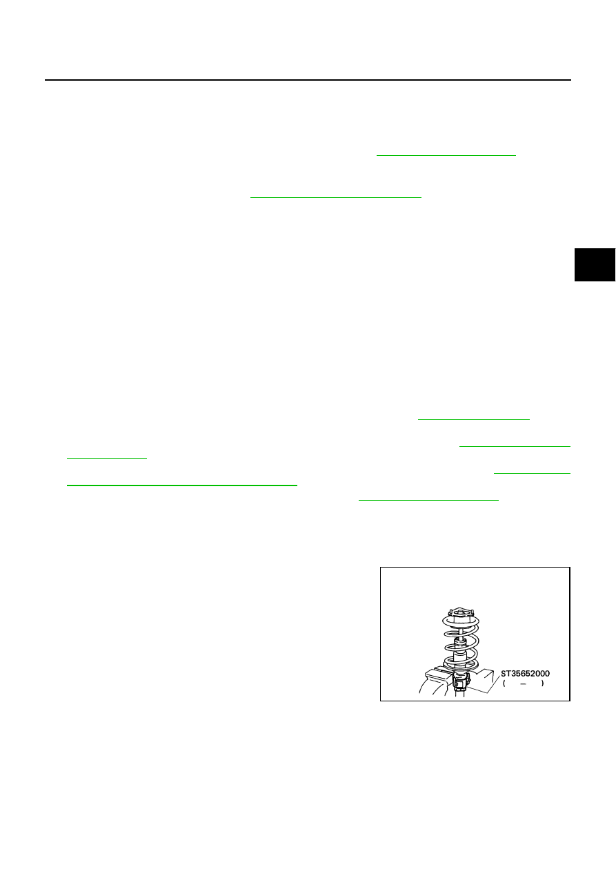
1.

Install strut attachment [SST] to shock absorber and secure it in
a vise.

CAUTION:

When installing the strut attachment to shock absorber,
wrap a shop cloth around strut to protect it from damage.

SEIA0296E

FSU-30

[AWD]

COIL SPRING AND SHOCK ABSORBER

2.

Using a spring compressor (commercial service tool), compress
coil spring between rubber seat and spring lower seat (on shock
absorber) until coil spring with a spring compressor is free.

CAUTION:

Be sure a spring compressor is securely attached coil
spring. Compress coil spring

3.

Make sure coil spring with a spring compressor between rubber
seat and spring lower seat (shock absorber) is free and then
remove piston rod lock nut while securing the piston rod tip so
that piston rod does not turn.

4.

Remove shock absorber mounting bracket, rubber seat, bound
bumper from shock absorber.

5.

Remove coil spring with a spring compressor, and then gradually release a spring compressor.

CAUTION:

Loosen while making sure coil spring attachment position does not move.

6.

Remove the strut attachment from shock absorber.

INSPECTION AFTER DISASSEMBLY
Shock Absorber Inspection

Check the following:

Shock absorber for deformation, cracks or damage, and replace it if a malfunction is detected.

Piston rod for damage, uneven wear or distortion, and replace it if a malfunction is detected.

For oil leakage, and replace it if a malfunction is detected. 

Shock Absorber Mounting Bracket and Rubber Parts Inspection

Check shock absorber mounting bracket for cracks and rubber parts for wear. Replace it if a malfunction is
detected

Coil Spring Inspection

Check coil spring for cracks, wear or damage, and replace it if a malfunction is detected. 

ASSEMBLY

CAUTION:

Do not damage shock absorber piston rod when installing components to shock absorber.

1.

Install strut attachment [SST] to shock absorber and secure it in
a vise.

CAUTION:

When installing the strut attachment to shock absorber,
wrap a shop cloth around strut to protect it from damage.

2.

Compress coil spring using a spring compressor (commercial
service tool), and install it onto shock absorber.

SEIA0297E

SEIA0296E

SEIA0297E

COIL SPRING AND SHOCK ABSORBER

FSU-31

[AWD]

C

D

F

G

H

I

J

K

L

M

A

B

FSU

CAUTION:

Install coil spring as shown in the figure with large diame-
ter side [100 mm (3.94 in)] up and small diameter side [90
mm (3.54 in)] down. (Distinction marks are 4.75 and 5.75
turn from the lower side end.)

Be sure a spring compressor is securely attached to coil
spring. Compress coil spring.

3.

Apply soapy water to bound bumper. Insert bound bumper into
shock absorber mounting bracket, and then install it to shock
absorber together with rubber seat.

CAUTION:

Do not use machine oil.

Install shock absorber mounting bracket as shown in the fig-
ure.

CAUTION:

Coil spring is securely seated in spring mounting groove
of rubber seat.

The bottom part of spring should be at the position of A
point of spring seat.

4.

Secure piston rod tip so that piston rod does not turn, then
tighten piston rod lock nut with specified torque.

5.

Gradually release a spring compressor, and remove coil spring.

CAUTION:

Loosen while making sure coil spring attachment position
does not move.

6.

Remove the strut attachment from shock absorber.

SEIA0661E

SEIA0662E

FSU-32

[AWD]

TRANSVERSE LINK

TRANSVERSE LINK

PFP:54500

Removal and Installation

NES000IW

REMOVAL

1.

Remove tires from vehicle with a power tool.

2.

Remove undercover with a power tool.

3.

Remove the mounting nut on the upper side of stabilizer connecting rod with a power tool, and then
remove stabilizer connecting rod from transverse link.

4.

Remove the mounting nut and bolt on the lower side of shock absorber arm with a power tool, and then
remove shock absorber arm from transverse link.

5.

Remove front cross bar. Refer to 

FSU-26, "Components"

 .

6.

Remove transverse link from steering knuckle. Refer to 

FAX-5, "Removal and Installation"

 .

7.

Remove mounting nuts and bolts, and then remove transverse link from vehicle.

INSPECTION AFTER REMOVAL
Visual Inspection

Check the following:

Transverse link and bushing for deformation, cracks or damage. Replace it if a malfunction is detected.

Ball joint boot for cracks or other damage, and also for grease leakage. Replace it if a malfunction is
detected.

Ball Joint Inspection

Manually move ball stud to confirm it moves smoothly with no binding.

Swing Torque Inspection

NOTE:
Before measurement, move ball stud at least ten times by hand to check for smooth movement.

Hook a spring balance at cotter pin mounting hole. Confirm
spring balance measurement value is within specifications when
ball stud begins moving.

If it is outside the specified range, replace transverse link
assembly.

Rotating Torque Inspection

Attach mounting nut to ball stud. Make sure that rotating torque
is within specifications with a preload gauge [SST].

If it is outside the specified range, replace transverse link
assembly.

Axial End Play Inspection

Move tip of ball stud in axial direction to check for looseness.

If it is outside the specified range, replace transverse link assembly.

Swing torque

: 0.5 - 3.6 N·m (0.06 - 0.36 kg-m, 5 - 31 in-lb)

Spring balance measurement

: 7.8 - 56.3 N (0.8 - 5.7 kg, 1.8 - 12.5 lb)

SEIA0523E

Rotating torque

: 0.5 - 3.9 N·m (0.06 - 0.39 kg-m, 5 - 34 in-lb)

SDIA1150E

Axial end play

: 0 mm (0 in)


Content   ..  781  782  783  784   ..