Infiniti M35/M45 Y50. Manual - part 766


  Index      Infiniti     Infiniti M35/M45 Y50 - service repair manual 2007 year


Search            copyright infringement  


Content   ..  764  765  766  767   ..


Infiniti M35/M45 Y50. Manual - part 766


SIDE OIL SEAL

FFD-11

C

E

F

G

H

I

J

K

L

M

A

B

FFD

SIDE OIL SEAL

PFP:33142

Removal and Installation

NDS000ET

NOTE:
Left side oil seal is attached to engine assembly. Replace it after removing front final drive assembly
from vehicle.

REMOVAL
Right Side:

1.

Remove the front drive shaft. Refer to 

FAX-11, "Removal and Installation"

 .

2.

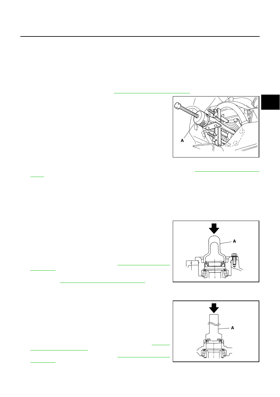
Remove the side oil seal using a puller.

CAUTION:

Be careful not to damage gear carrier.

Left Side:

1.

Remove the front final drive assembly from vehicle with power tool. Refer to 

FFD-13, "Removal and Instal-

lation"

 .

2.

Remove the side oil seal using a flat-bladed screwdriver.

CAUTION:

Be careful not to damage gear carrier.

INSTALLATION
Right Side:

1.

Apply multi-purpose grease to sealing lips of side oil seal.

2.

Using the drift, press-fit side oil seal so that its surface comes
face to face with the end surface of the side retainer.

CAUTION:

Do not reuse oil seal.

When installing, do not incline oil seal.

3.

Install the front drive shaft. Refer to 

FAX-11, "Removal and

Installation"

 .

4.

When oil leaks while removing, check oil level after the installa-
tion. Refer to 

FFD-8, "Checking Differential Gear Oil"

 .

Left Side:

1.

Apply multi-purpose grease to sealing lips of side oil seal.

2.

Using the drift, press-fit side oil seal so that its surface comes
face to face with the end surface of the gear carrier.

CAUTION:

Do not reuse oil seal.

When installing, do not incline oil seal.

3.

Install the front final drive assembly on vehicle. Refer to

FFD-13,

"Removal and Installation"

 .

4.

Install the front drive shaft. Refer to 

FAX-11, "Removal and

Installation"

 .

Tool number

A: KV381054S0 (J-34286)

PDIA0838J

Tool number

A: ST33400001 (J-26082)

PDIA0787J

Tool number

A: KV38102100 (J-25803-01)

PDIA0788J

FFD-12

SIDE OIL SEAL

5.

When oil leaks while removing, check oil level after the installation. Refer to 

FFD-8, "Checking Differential

Gear Oil"

 .

FRONT FINAL DRIVE ASSEMBLY

FFD-13

C

E

F

G

H

I

J

K

L

M

A

B

FFD

FRONT FINAL DRIVE ASSEMBLY

PFP:38500

Removal and Installation

NDS000EU

COMPONENTS

REMOVAL

1.

Remove front drive shaft both. Refer to 

FAX-11, "Removal and Installation"

 .

2.

Remove front crossbar with power tool.

3.

Separate steering outer socket and steering knuckle. Refer to 

PS-19, "POWER STEERING GEAR AND

LINKAGE"

 .

4.

Remove side shaft.

5.

Remove three way catalyst (right bank) with power tool. Refer to 

EX-3, "EXHAUST SYSTEM"

 .

6.

Remove front propeller shaft. Refer to 

PR-5, "Removal and Installation"

 .

7.

Separate EPS solenoid valve connector.

8.

Separate power steering hydraulic line.

9.

Remove stabilizer assembly with power tool. Refer to 

FSU-36, "Removal and Installation"

 .

10. Separate steering lower joint and steering gear assembly. Refer to 

PS-19, "POWER STEERING GEAR

AND LINKAGE"

 .

11. Set a suitable jack to engine.

12. Remove front suspension member with power tool. Refer to 

FSU-27, "Removal and Installation"

 .

13. Remove breather hose and tube.

14. Remove engine mounting bracket (RH) (Lower) and engine mounting insulator (RH) with power tool.

Refer to 

EM-119, "Removal and Installation (AWD Models)"

 .

1.

Front final drive assembly

2.

Side shaft

3.

Bushing

4.

Front propeller shaft

5.

Breather hose

6.

Breather tube

7.

Breather connector

8.

Engine mounting bracket (RH) 
(Lower)

9.

Engine mounting insulator (RH)

Refer to 

GI-11, "Components"

 , for the symbols in the figure.

PDIA0789J

FFD-14

FRONT FINAL DRIVE ASSEMBLY

15. Remove front final drive assembly with power tool.

INSTALLATION

Note the following, and installation is in the reverse order of removal.

Refer to 

FFD-13, "COMPONENTS"

  about each tightening torque.

When installing the side shaft, apply multi-purpose grease to contact surface of side shaft and side shaft
oil seal.

Tighten mounting bolts in the order as described below when
installing front final drive assembly: side of gear carrier (1),
upper side of gear carrier (2), part of carrier cover (3), lower part
of gear carrier (4).

CAUTION:

Align the mating faces of gear carrier and oil pan for instal-
lation.

When installing breather hoses (1) and tube (2), refer to the fig-
ure.

CAUTION:

Make sure there are no pinched or restricted areas on the
breather hose caused by bending or winding when install-
ing it.

Make sure the paint mark facing up (

).

Securely install the hose until it seats the rounded portion of the
tube (

).

Install breather connector as shown in the figure.

Seat the breather tube bracket end (A) to the machined face (B)
of gear carrier boss.

When oil leaks while removing final drive assembly, check oil
level after the installation. Refer to 

FFD-8, "Checking Differential

Gear Oil"

 .

PDIA0839J

PDIA0790J

Angle “A”:

0 - 30

°

PDIA0841J

PDIA0842E


Content   ..  764  765  766  767   ..