Infiniti M35/M45 Y50. Manual - part 654


  Index      Infiniti     Infiniti M35/M45 Y50 - service repair manual 2007 year


Search            copyright infringement  


Content   ..  652  653  654  655   ..


Infiniti M35/M45 Y50. Manual - part 654


DTC P0420, P0430 THREE WAY CATALYST FUNCTION

EC-1089

[VK45DE]

C

D

E

F

G

H

I

J

K

L

M

A

EC

DTC P0420, P0430 THREE WAY CATALYST FUNCTION

PFP:20905

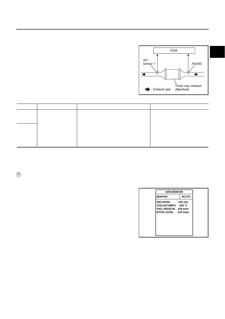
On Board Diagnosis Logic

NBS005GS

The ECM monitors the switching frequency ratio of air fuel ratio (A/F)
sensor 1 and heated oxygen sensor 2.
A three way catalyst (manifold) with high oxygen storage capacity
will indicate a low switching frequency of heated oxygen sensor 2.
As oxygen storage capacity decreases, the heated oxygen sensor 2
switching frequency will increase.
When the frequency ratio of A/F sensor 1 and heated oxygen sensor
2 approaches a specified limit value, the three way catalyst (mani-
fold) malfunction is diagnosed.

DTC Confirmation Procedure

NBS005GT

NOTE:
If DTC Confirmation Procedure has been previously conducted, always turn ignition switch OFF and wait at
least 10 seconds before conducting the next test.

 WITH CONSULT-II

TESTING CONDITION:
Do not hold engine speed for more than the specified minutes below.

1.

Turn ignition switch ON and select “DATA MONITOR” mode with
CONSULT-II.

2.

Start engine and warm it up to the normal operating tempera-
ture.

3.

Turn ignition switch OFF and wait at least 10 seconds.

4.

Start engine and keep the engine speed between 3,500 and
4,000 rpm for at least 1 minute under no load.

5.

Let engine idle for 1 minute.

6.

Make sure that “COOLAN TEMP/S” indicates more than 70

°

C

(158

°

F).

If not, warm up engine and go to next step when “COOLAN
TEMP/S” indication reaches to 70

°

C (158

°

F).

7.

Open engine hood.

PBIB2055E

DTC No.

Trouble diagnosis name

DTC detecting condition

Possible cause

P0420
0420
(Bank 1)

Catalyst system efficiency 
below threshold

Three way catalyst (manifold) does not operate 
properly.

Three way catalyst (manifold) does not have 
enough oxygen storage capacity.

Three way catalyst (manifold)

Exhaust tube

Intake air leaks

Fuel injector

Fuel injector leaks

Spark plug

Improper ignition timing

P0430
0430
(Bank 2)

SEF189Y

EC-1090

[VK45DE]

DTC P0420, P0430 THREE WAY CATALYST FUNCTION

8.

Select “DTC & SRT CONFIRMATION” then “SRT WORK SUP-
PORT” mode with CONSULT-II.

9.

Rev engine up to 2,000 to 3,000 rpm and hold it for 3 consecu-
tive minutes, then release the accelerator pedal completely.
If “INCMP” of “CATALYST” changed to “CMPLT”, go to step 12.

10. Wait 5 seconds at idle.

11. Rev engine up to 2,000 to 3,000 rpm and maintain it until

“INCMP” of “CATALYST” changes to “CMPLT” (It will take
approximately 5 minutes).
If not “CMPLT”, stop engine and cool it down to less than 70

°

C

(158

°

F) and then retest from step 1.

12. Select “SELF-DIAG RESULTS” mode with CONSULT-II.

13. Confirm that 1st trip DTC is not detected.

If 1st trip DTC is detected, go to 

EC-1091, "Diagnostic Proce-

dure"

 .

Overall Function Check

NBS005GU

Use this procedure to check the overall function of the three way catalyst (manifold). During this check, a 1st
trip DTC might not be confirmed.

 WITH GST

1.

Start engine and warm it up to the normal operating temperature.

2.

Turn ignition switch OFF and wait at least 10 seconds.

3.

Start engine and keep the engine speed between 3,500 and 4,000 rpm for at least 1 minute under no load.

4.

Let engine idle for 1 minute.

5.

Open engine hood.

6.

Set voltmeter probe between ECM terminal 55 [HO2S2 (bank 1)
signal] and ground, ECM terminal 74 [HO2S2 (bank 2) signal]
and ground.

7.

Keep engine speed at 2,500 rpm constant under no load.

8.

Make sure that the voltage does not vary for more than 5 sec-
onds.
If the voltage fluctuation cycle takes less than 5 seconds, go to

EC-1091, "Diagnostic Procedure"

 .

1 cycle: 0.6 - 1.0 

 0 - 0.3 

 0.6 - 1.0

PBIB1784E

PBIB1785E

SEF535Z

PBIB2056E

DTC P0420, P0430 THREE WAY CATALYST FUNCTION

EC-1091

[VK45DE]

C

D

E

F

G

H

I

J

K

L

M

A

EC

Diagnostic Procedure

NBS005GV

1. 

CHECK EXHAUST SYSTEM

Visually check exhaust tubes and muffler for dent.
OK or NG

OK

>> GO TO 2.

NG

>> Repair or replace.

2. 

CHECK EXHAUST GAS LEAK

1.

Start engine and run it at idle.

2.

Listen for an exhaust gas leak before the three way catalyst (manifold).

OK or NG

OK

>> GO TO 3.

NG

>> Repair or replace.

3. 

CHECK INTAKE AIR LEAK

Listen for an intake air leak after the mass air flow sensor.

OK or NG

OK

>> GO TO 4.

NG

>> Repair or replace.

4. 

CHECK IGNITION TIMING

Check the following items. Refer to 

EC-780, "Basic Inspection"

 .

OK or NG

OK

>> GO TO 5.

NG

>> Follow th

EC-780, "Basic Inspection"

 .

PBIB1216E

Items

Specifications

Target idle speed

650 

±

 50 rpm (in P or N position)

Ignition timing

12 

±

 5

°

 BTDC (in P or N position)

EC-1092

[VK45DE]

DTC P0420, P0430 THREE WAY CATALYST FUNCTION

5. 

CHECK FUEL INJECTORS

1.

Stop engine and then turn ignition switch ON.

2.

Check voltage between ECM terminals 21, 22, 23, 40, 41, 42,
44, 63 and ground with CONSULT-II or tester.
Refer to Wiring Diagram for fuel injectors, 

EC-1390, "Wiring Dia-

gram"

 .

OK or NG

OK

>> GO TO 6.

NG

>> Perfor

EC-1391, "Diagnostic Procedure"

 .

6. 

CHECK FUNCTION OF IGNITION COIL-I

CAUTION:

Do the following procedure in the place where ventilation is good without the combustible.

1.

Turn ignition switch OFF.

2.

Remove fuel pump fuse (1) in IPDM E/R (2) to release fuel pres-
sure.

NOTE:
Do not use CONSULT-II to release fuel pressure, or fuel pres-
sure applies again during the following procedure.

3.

Start engine.

4.

After engine stalls, crank it two or three times to release all fuel
pressure.

5.

Turn ignition switch OFF.

6.

Remove all ignition coil harness connectors to avoid the electri-
cal discharge from the ignition coils.

7.

Remove ignition coil and spark plug of the cylinder to be checked.

8.

Crank engine for 5 seconds or more to remove combustion gas in the cylinder.

9.

Connect spark plug and harness connector to ignition coil.

10. Fix ignition coil using a rope etc. with gap of 13 - 17 mm

between the edge of the spark plug and grounded metal portion
as shown in the figure.

11. Crank engine for about 3 seconds, and check whether spark is

generated between the spark plug and the grounded metal por-
tion.

CAUTION:

Do not approach to the spark plug and the ignition coil
within 50cm. Be careful not to get an electrical shock
while checking, because the electrical discharge voltage
becomes 20kV or more.

It might cause to damage the ignition coil if the gap of more than 17 mm is taken.

NOTE:
When the gap is less than 13 mm, the spark might be generated even if the coil is malfunctioning.

OK or NG

OK

>> GO TO 10.

NG

>> GO TO 7.

Battery voltage should exist.

PBIB1527E

Spark should be generated.

PBIB2697E

PBIB2325E


Content   ..  652  653  654  655   ..