Infiniti M35/M45 Y50. Manual - part 655
DTC P0420, P0430 THREE WAY CATALYST FUNCTION
EC-1093
[VK45DE]
C
D
E
F
G
H
I
J
K
L
M
A
EC
7.
CHECK FUNCTION OF IGNITION COIL-II
1.
Turn ignition switch OFF.
2.
Disconnect spark plug and connect a known-good spark plug.
3.
Crank engine for about 3 seconds, and recheck whether spark is generated between the spark plug and
the grounded metal portion.
OK or NG
OK
>> GO TO 8.
NG
>> Check ignition coil, power transistor and their circuits. Refer to
8.
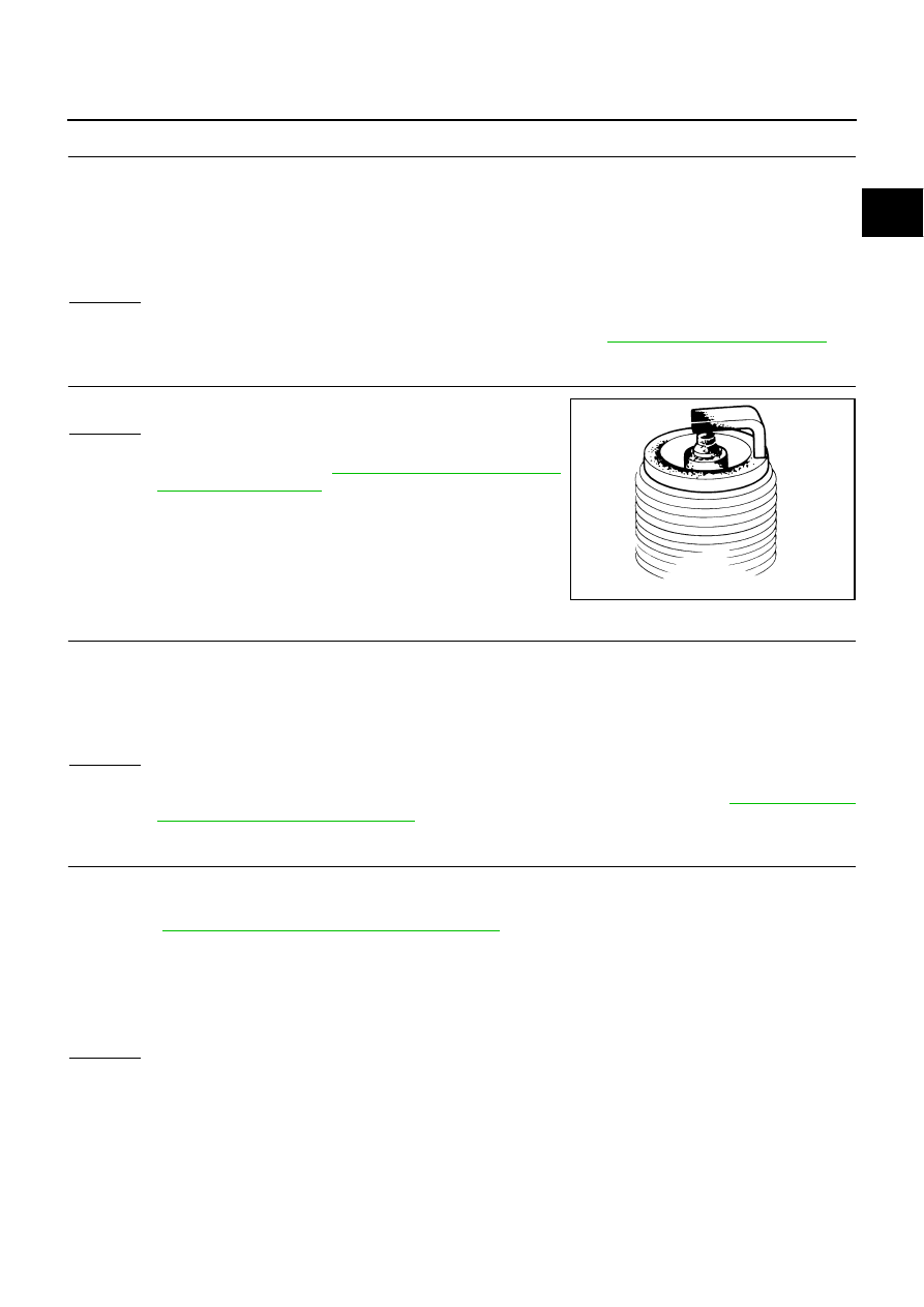
CHECK SPARK PLUG
Check the initial spark plug for fouling, etc.
OK or NG
OK
>> Replace spark plug(s) with standard type one(s). For
spark plug type, refer to
NG
>> 1. Repair or clean spark plug.
2. GO TO 9.
9.
CHECK FUNCTION OF IGNITION COIL-III
1.
Reconnect the initial spark plugs.
2.
Crank engine for about 3 seconds, and recheck whether spark is generated between the spark plug and
the grounded portion.
OK or NG
OK
>> INSPECTION END
NG
>> Replace spark plug(s) with standard type one(s). For spark plug type, refer to
.
10.
CHECK FUEL INJECTOR
1.
Turn ignition switch OFF.
2.
Remove fuel tube assembly.
Refer to
EM-193, "FUEL INJECTOR AND FUEL TUBE"
.
Keep fuel hose and all fuel injectors connected to fuel tube.
3.
Disconnect all ignition coil harness connectors.
4.
Reconnect all fuel injector harness connectors disconnected.
5.
Turn ignition switch ON.
Make sure fuel does not drip from fuel injector.
OK or NG
OK (Does not drip.)>>GO TO 11.
NG (Drips.)>>Replace the fuel injector(s) from which fuel is dripping.
Spark should be generated.
SEF156I
Spark should be generated.