Infiniti M35/M45 Y50. Manual - part 652
DTC P0335 CKP SENSOR (POS)
EC-1081
[VK45DE]
C
D
E
F
G
H
I
J
K
L
M
A
EC
Component Inspection
NBS005GJ
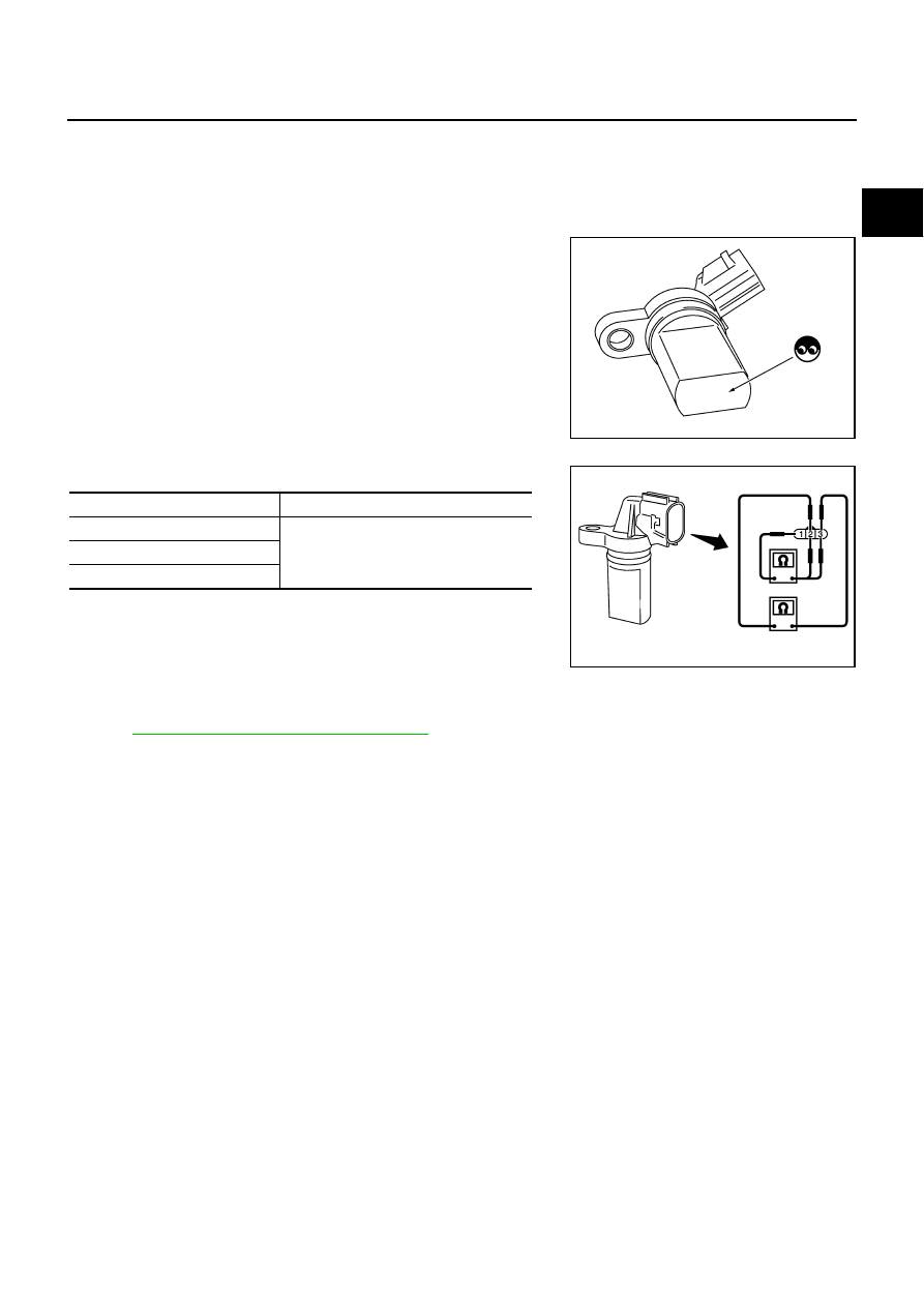
CRANKSHAFT POSITION SENSOR (POS)
1.
Loosen the fixing bolt of the sensor.
2.
Disconnect crankshaft position sensor (POS) harness connector.
3.
Remove the sensor.
4.
Visually check the sensor for chipping.
5.
Check resistance as shown in the figure.
Removal and Installation
NBS005GK
CRANKSHAFT POSITION SENSOR (POS)
Refer to
EM-187, "OIL PAN AND OIL STRAINER"
.
PBIB0563E
Terminal No. (Polarity)
Resistance
Ω
[at 25
°
C (77
°
F)]
1 (+) - 2 (-)
Except 0 or
∞
1 (+) - 3 (-)
2 (+) - 3 (-)
PBIB0564E