Infiniti M35/M45 Y50. Manual - part 369
WARNING CHIME
DI-59
C
D
E
F
G
H
I
J
L
M
A
B
DI
WARNING CHIME
PFP:24814
System Description
NKS003UY
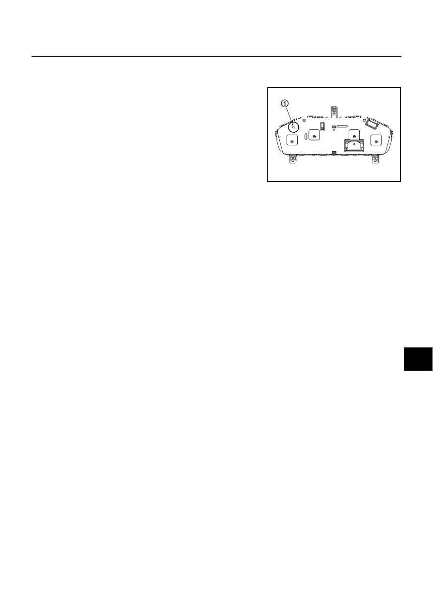
●
The buzzer (1) for warning chime system is installed in the com-
bination meter.
●
The buzzer sounds when the combination meter receives
buzzer output signal from each unit through unified meter and A/
C amp.
POWER SUPPLY AND GROUND CIRCUIT
Power is supplied at all times
●
through 50A fusible link (letter F , located in the fuse and fusible link block)
●
to BCM terminal 55,
●
through 10A fuse [No. 21, located in the fuse block (J/B)]
●
to BCM terminal 42, and
●
to combination meter terminal 23,
●
through 10A fuse [No. 19, located in the fuse block (J/B)]
●
to unified meter and A/C amp. terminal 54.
When ignition switch is in ON or START position, power is supplied
●
through 15A fuse [No. 1, located in the fuse block (J/B)]
●
to BCM terminal 38,
●
through 10A fuse [No. 12, located in the fuse block (J/B)]
●
to unified meter and A/C amp. terminal 53,
●
through 10A fuse [No. 14, located in the fuse block (J/B)]
●
to combination meter terminal 12.
Ground is supplied
●
to BCM terminals 52,
●
to unified meter and A/C amp. terminals 55 and 71, and
●
to combination meter terminals 9, 10 and 11,
●
through grounds M16 and M70.
SKIB2633J