Infiniti M35/M45 Y50. Manual - part 226
REMOVAL AND INSTALLATION
AV-281
[WITH MOBILE ENTERTAINMENT SYSTEM]
C
D
E
F
G
H
I
J
L
M
A
B
AV
3.
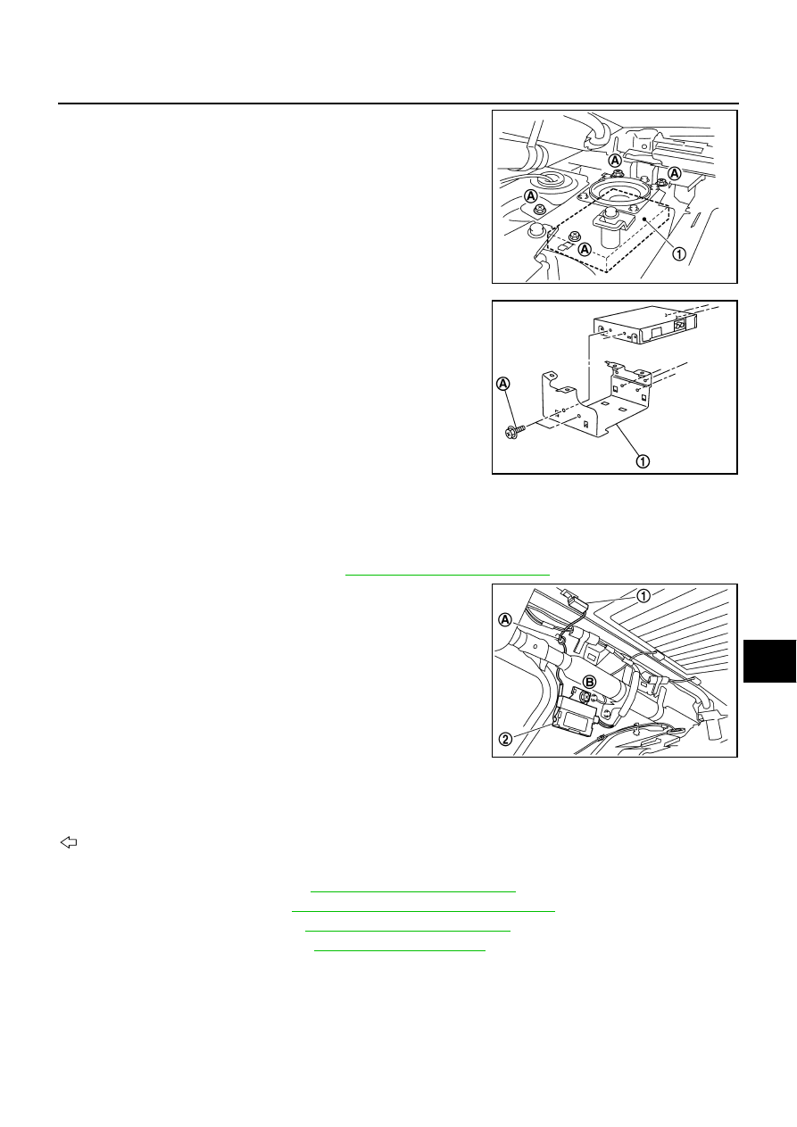
Remove screws (A).
4.
Disconnect connector and remove satellite radio tuner (1) from
trunk room side.
5.
Disconnect screws (A), and remove bracket (1).
INSTALLATION
Installation is the reverse order of removal.
Antenna Amp
NKS004BS
REMOVAL
1.
Remove rear pillar finisher (RH). Refer to
EI-37, "Removal and Installation"
2.
Disengaged the clip (A) to separate glass terminal (1).
3.
Remove screw (B) and remove antenna amp (2) from vehicle.
INSTALLATION
Installation is the reverse order of removal.
Satellite Radio Antenna
NKS004BT
: Vehicle front
REMOVAL
1.
Remove rear pillar finisher. Refer to
EI-37, "Removal and Installation"
2.
Remove personal lamp. Refer to
LT-289, "REMOVAL AND INSTALLATION"
3.
Remove assist grip (rear). Refer to
EI-52, "Removal and Installation"
4.
Remove rear display cover. Refer to
5.
Remove head lining assembly (rear) to obtain work space between the head lining assembly and vehicle.
SKIB4396E
SKIB8875E
SKIB4344E