Infiniti M35/M45 Y50. Manual - part 128
TROUBLE DIAGNOSIS
ATC-63
C
D
E
F
G
H
I
K
L
M
A
B
ATC
AUXILIARY MECHANISM: TEMPERATURE SETTING TRIMMER
The trimmer compensates for differences in range of
±
3
°
C (
±
6
°
F) between temperature setting (displayed dig-
itally) and temperature felt by customer.
Operating procedures for this trimmer are as follows:
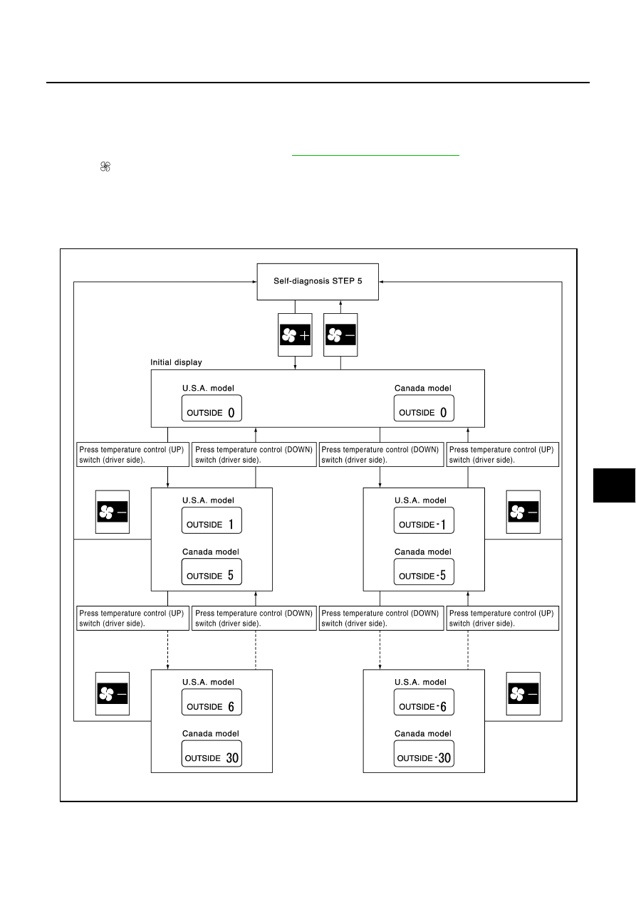
1.
Begin self-diagnosis STEP-5 mode. Refer to
ATC-56, "Self-diagnosis Function"
.
2.
Press (fan) UP switch to set system in auxiliary mode.
3.
Display shows “61” in auxiliary mechanism. It takes approximately 3 seconds to enable setting operation.
4.
Press temperature control switch (driver side) as desired. Temperature will change at a rate of 0.5
°
C
(1.0
°
F) each time a switch is pressed.
CAUTION:
A decimal point is not indicated on the display.
When battery cable is disconnected or battery voltage is below 10 V, trimmer operation is canceled. Tempera-
ture set becomes that of initial condition, i.e. 0
°
C (0
°
F).
SJIA1693E