Infiniti M35/M45 Y50. Manual - part 126


  Index      Infiniti     Infiniti M35/M45 Y50 - service repair manual 2007 year


Search            copyright infringement  


Content   ..  124  125  126  127   ..


Infiniti M35/M45 Y50. Manual - part 126


TROUBLE DIAGNOSIS

ATC-55

C

D

E

F

G

H

I

K

L

M

A

B

ATC

65

O

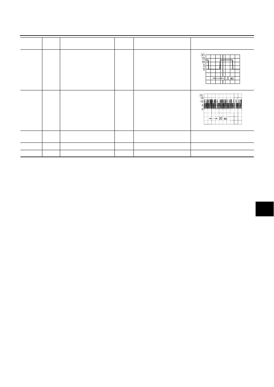
ECV (Electric Control Valve) 
signal

ON

Self-diagnosis. STEP-4
(Code No. 45)

69

R

A/C LAN signal

ON

70

W

Power supply for each door 
motor

ON

Battery voltage

71

B

Ground (Power)

ON

Approx. 0

72

P

CAN-L

Terminal 

No.

Wire 

color

Item

Ignition 

switch

Condition

Voltage

(V)

SJIA1607E

SJIA1453J

ATC-56

TROUBLE DIAGNOSIS

Self-diagnosis Function

NJS000GJ

DESCRIPTION

The self-diagnosis system diagnoses sensors, door motors, blower motor, etc. by system line. Refer to appli-
cable sections (items) for details. Shifting from normal control to the self-diagnosis system is accomplished by
starting the engine (turning the ignition switch ON) and pressing OFF switch for at least 5 seconds. The OFF
switch must be pressed within 10 seconds after starting the engine (ignition switch is turned ON). This system
will be canceled by either pressing AUTO switch or turning the ignition switch OFF. Shifting from one step is
accomplished by means of pressing temperature control switch (driver side), as required.
Shifting from STEP-5 to AUXILIARY MECHANISM is accomplished by means of pressing   (fan) UP switch.

RJIA4034E

TROUBLE DIAGNOSIS

ATC-57

C

D

E

F

G

H

I

K

L

M

A

B

ATC

FUNCTION CONFIRMATION PROCEDURE

1. 

SET IN SELF-DIAGNOSIS MODE

1.

Turn ignition switch ON.

2.

Set in self-diagnosis mode as follows. Within 10 seconds after starting engine (ignition switch is turned
ON.), press OFF switch for at least 5 seconds.

NOTE:

If battery voltage drops below 12 V during diagnosis STEP-3, door motor speed becomes slower and as a
result, the system may generate an error even when operation is normal. To avoid this, start engine before
performing this diagnosis.

Former STEP-1 (LEDs and display screen are checked) does not exist in this self-diagnosis function.

>> GO TO 2.

2. 

STEP-2: SENSOR CIRCUITS ARE CHECKED FOR OPEN OR SHORT CIRCUIT

Does code No. 20 appear on the display?

YES

>> GO TO 3.

NO

>> GO TO 13.

3. 

CHECK TO ADVANCE SELF-DIAGNOSIS STEP-3

Press temperature control (UP) switch (driver side).

Advance to self-diagnosis STEP-3?

YES

>> GO TO 4.

NO

>> Replace Multifunction switch. (Temperature control switch is malfunctioning.)

4. 

CHECK TO RETURN SELF-DIAGNOSIS STEP-2

Press temperature control (DOWN) switch (driver side).
Return to self-diagnosis STEP-2?

YES

>> GO TO 5.

NO

>> Malfunctioning multifunction switch or unified meter and A/C amp. Refer to 

ATC-110, "Self-diagno-

sis"

 .

5. 

STEP-3: MODE DOOR AND INTAKE DOOR POSITIONS ARE CHECKED

Press temperature control (UP) switch (driver side).
Does code No. 30 appear on the display?

YES

>> GO TO 6.

NO

>> GO TO 14.

SJIA1778E

SJIA1779E

ATC-58

TROUBLE DIAGNOSIS

6. 

STEP-4: OPERATION OF EACH DOOR MOTOR IS CHECKED

1.

Press temperature control (UP) switch (driver side).

2.

Press 

 (DEF) switch. Code No. of each door motor test is

indicated on the display.

>> GO TO 7.

7. 

CHECK ACTUATORS

Refer to the following chart and check discharge air flow, air temperature, blower motor duty ratio and com-
pressor operation.

SJIA1780E

RJIA4035E

Code No.

41

42

43

44

45

46

Mode door position

VENT

B/L 1

B/L 2

FOOT

*1

D/F

DEF

Upper ventilator door 
position

OPEN

SHUT

SHUT

SHUT

SHUT

SHUT

Intake door position

REC

REC

20% FRE

FRE

FRE

FRE

Air mix door position

FULL COLD

FULL COLD

FULL HOT

FULL HOT

FULL HOT

FULL HOT

Blower motor duty ratio

37%

91%

65%

65%

65%

91%

Compressor

ON

ON

OFF

OFF

ON

ON

Electronic control valve 
(ECV) duty ratio

100%

100%

0%

0%

50%

100%


Content   ..  124  125  126  127   ..