Infiniti M35/M45 Y50. Manual - part 118
REFRIGERATION SYSTEM
ATC-23
C
D
E
F
G
H
I
K
L
M
A
B
ATC
Operation
1.
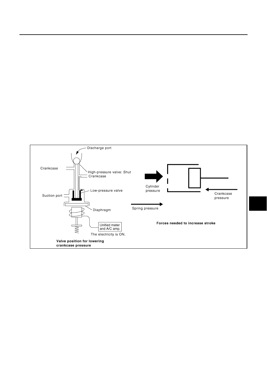
Control Valve
–
By changing high-pressure valve lift amount, built-in electronic control valve executes the following:
•
Controls high-pressure valve discharge amount.
•
Changes crankcase pressure in compressor.
•
Changes angle of swash plate.
–
Amount of high-pressure valve lift is determined by factors below.
•
Low-pressure applied to diaphragm
•
Spring load of set spring
•
Balance of magnetic force generated in magnet coil
–
Electronic control valve (ECV) magnet coil receives electric signal (duty control) from unified meter and A/
C amp. Then, magnetic force generated by electric current is changed to control high-pressure valve lift
amount.
2.
Maximum Cooling
High-pressure valve is closed by magnetic force generated by electric signal sent from unified meter and
A/C amp. At this time, cylinder moves full stroke due to pressure balance between inside crankcase (Pc)
and suction line (Ps).
Under this condition, the swash plate is set to the maximum stroke position.
3.
Capacity Control
When no electric signal is sent from unified meter and A/C amp. (current: OFF), high-pressure valve is
opened by spring force.
Since suction pressure is low, it makes the suction port close and the discharge port open. Thus, crank-
case pressure becomes high as high-pressure enters the crankcase.
–
The force acts around the link near the swash plate, and is generated by the pressure difference before
and behind the piston.
–
The thrust flange and link are located where the piston generates the highest pressure. Piston pressure is
between suction pressure Ps and discharge pressure Pd, which is close to suction pressure Ps. If crank-
case pressure Pc rises due to capacity control, the force around the link makes the swash plate angle
decrease and also the piston stroke decrease. In other words, crankcase pressure increase triggers pres-
SJIA0547E