Content .. 1112 1113 1114 1115 ..
Infiniti M35/M45 Y50. Manual - part 1114
REAR ACTIVE STEER
STC-13
[RAS]
C
D
E
F
H
I
J
K
L
M
A
B
STC
[RAS]
REAR ACTIVE STEER
PFP:55705
Removal and Installation
NGS000E5
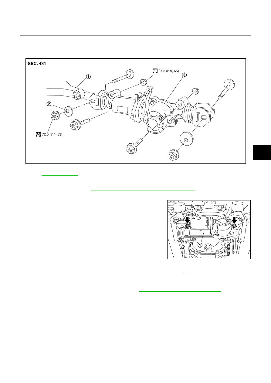
COMPONENTS
REMOVAL
1.
Remove coil spring. Refer to
RSU-16, "REAR LOWER LINK & COIL SPRING"
2.
Disconnect harness connector from RAS actuator assembly and rear suspension member.
3.
Remove fixing bolts and nuts of RAS actuator assembly (1), and
then remove RAS actuator assembly (1) from rear suspension
member.
INSTALLATION
●
Installation is the reverse order of removal. For tightening torque, refer to
.
●
When installing RAS actuator assembly to rear suspension member, check the mounting surfaces of RAS
actuator assembly and rear suspension member for oil, dirt, sand, or other foreign materials.
●
To perform the neutral position adjustment. Refer to
STC-14, "Neutral Position Adjustment"
1.
Rear lower link
2.
Decenter cam
3.
RAS actuator assembly
Refer to
, for the symbols in the figure.
SGIA1238E
SGIA1239E