Infiniti M35/M45 Y50. Manual - part 1066


  Index      Infiniti     Infiniti M35/M45 Y50 - service repair manual 2007 year


Search            copyright infringement  


Content   ..  1064  1065  1066  1067   ..


Infiniti M35/M45 Y50. Manual - part 1066


AUTOMATIC DRIVE POSITIONER

SE-61

C

D

E

F

G

H

J

K

L

M

A

B

SE

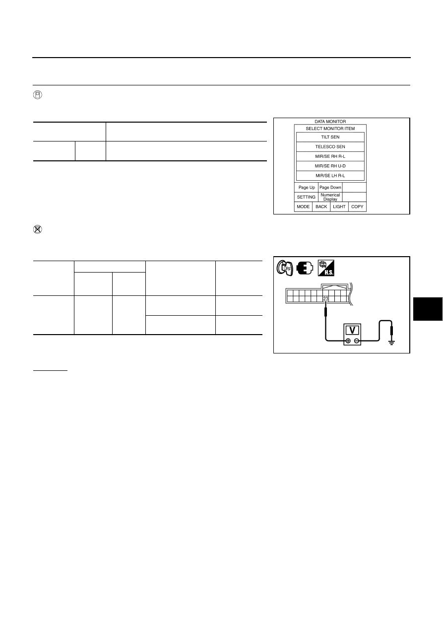
Check Telescopic Sensor Circuit 

NIS0026H

1. 

CHECK FUNCTION

With CONSULT-II

Operate the telescopic switch with “TELESCO SEN” on the DATA MONITOR to make sure the voltage
changes.

Without CONSULT-II

1.

Turn ignition switch OFF.

2.

Check voltage between automatic drive positioner control unit connector and ground.

OK or NG

OK

>> Telescopic sensor circuit is OK.

NG

>> GO TO 2.

Monitor item

 [OPERATION or UNIT]

Contents

TELESCO
SEN

“V”

The telescoping position (voltage) judged from the tele-
scoping sensor signal is displayed.

PIIA0295E

Automatic 

drive posi-

tioner con-

nector

Terminals

Condition

Voltage (V) 

(Approx.)

(+)

(–)

M6

23

Ground

Telescopic
top position

4.6

Telescopic 
bottom position

0.4

PIIB6159E

SE-62

AUTOMATIC DRIVE POSITIONER

2. 

CHECK HARNESS CONTINUITY

1.

Disconnect automatic drive positioner control unit connector and telescopic sensor connector. 

2.

Check continuity harness between automatic drive positioner
control unit connector and telescopic sensor connector.

3.

Check continuity harness between automatic drive positioner
control unit connector and ground.

OK or NG

OK

>> GO TO 3.

NG

>> Repair or replace harness.

3. 

CHECK AUTOMATIC DRIVE POSITIONER CONTROL UNIT OUTPUT

1.

Connect automatic drive positioner control unit connector.

2.

Check voltage between automatic drive position control unit connector and ground.

OK or NG

OK

>> Replace telescopic sensor.

NG

>> Replace automatic drive positioner control unit.

A

B

Continuity 

Automatic drive 

positioner control 

unit connector

Terminal

Telescopic sensor 

connector

Terminal

M6

23

M44

2

Yes

M7

33

1

41

3

A

Ground

Continuity 

Automatic drive posi-

tioner control unit con-

nector

Terminal

M6

23

No

M7

33

41

PIIB6160E

Terminals

Voltage (V)

(Approx.)

(+)

(–)

Automatic drive 

positioner control 

unit connector

Terminal

M6

23

Ground

5

PIIB6159E

AUTOMATIC DRIVE POSITIONER

SE-63

C

D

E

F

G

H

J

K

L

M

A

B

SE

Check Tilt Sensor Circuit 

NIS0026I

1. 

CHECK TILT SENSOR

 With CONSULT-II

With “TILT SEN” on the DATA MONITOR, operate the tilt switch to make sure voltage changes.

 Without CONSULT-II

1.

Turn ignition switch OFF.

2.

Check voltage between automatic drive positioner control unit connector and ground.

OK or NG

OK

>> Tilt sensor circuit is OK.

NG

>> GO TO 2.

Monitor item

 [OPERATION or UNIT]

Contents

TILT SEN

“V”

The tilt position (voltage) judged from the tilt sensor sig-
nal is displayed.

PIIA0295E

Automatic 

drive posi-

tioner con-

trol unit 

connector

Terminals

Condition

Voltage (V) 

(Approx.)

(+)

(–)

M6

7

Ground

Tilt top position

1

Tilt bottom position

3.8

PIIB6161E

SE-64

AUTOMATIC DRIVE POSITIONER

2. 

CHECK HARNESS

1.

Disconnect automatic drive positioner control unit connector and tilt sensor connector.

2.

Check continuity harness between automatic drive positioner control unit connector and tilt sensor con-
nector.

3.

Automatic drive positioner control unit connector and ground.

OK or NG

OK

>> GO TO 3.

NG

>> Repair or replace harness.

3. 

CHECK AUTOMATIC DRIVE POSITIONER CONTROL UNIT OUTPUT

1.

Connect automatic drive positioner control unit connector.

2.

Check voltage between automatic drive position control unit connector and ground.

OK or NG

OK

>> Replace telescopic sensor.

NG

>> Replace automatic drive positioner control unit.

Check Door Mirror Sensor LH Circuit

NIS0026J

1. 

CHECK DOOR MIRROR FUNCTION

Check the following items.
Operation malfunction in memory operation. 

NOTE:
If a door mirror face position is set to an implausible angle, the set position may not be reproduced.
OK or NG

OK

>> GO TO 2.

NG

>> Repair or replace the malfunctioning parts, and check the symptom again.

A

B

Continuity 

Automatic drive 

positioner control 

unit connector

Terminal

Tilt sensor 

connector

Terminal

M6

7

M37

2

Yes

M7

33

3

41

1

A

Ground

Continuity 

Automatic drive posi-

tioner control unit con-

nector

Terminal

M6

7

No

M7

33

41

PIIB6162E

Terminals

Voltage (V)

(Approx.)

(+)

(–)

Automatic drive 

positioner control 

unit connector

Terminal

M6

7

Ground

5

PIIB6161E


Content   ..  1064  1065  1066  1067   ..