Infiniti M35/M45 Y50. Manual - part 1064


  Index      Infiniti     Infiniti M35/M45 Y50 - service repair manual 2007 year


Search            copyright infringement  


Content   ..  1062  1063  1064  1065   ..


Infiniti M35/M45 Y50. Manual - part 1064


AUTOMATIC DRIVE POSITIONER

SE-53

C

D

E

F

G

H

J

K

L

M

A

B

SE

4. 

CHECK AUTOMATIC DRIVE POSITIONER CONTROL UNIT OUTPUT SIGNAL

1.

Connect automatic drive positioner control unit connector and tilt motor connector.

2.

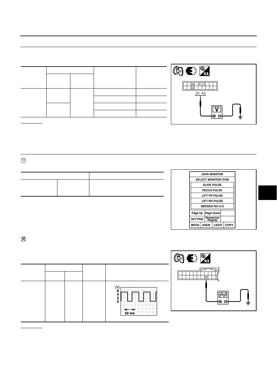
Check voltage between automatic drive positioner control unit connector and ground.

OK or NG

OK

>> Replace tilt motor.

NG

>> Replace automatic drive positioner control unit.

Check Sliding Sensor Circuit 

NIS0026D

1. 

CHECK FUNCTION

 With CONSULT-II

Check operation with “SLIDE PULSE” on the DATA MONITOR to make sure the pulse changes.

 Without CONSULT-II

1.

Turn ignition switch OFF.

2.

Check signal between driver seat control unit connector and
ground, with oscilloscope.

OK or NG

OK

>> Sliding sensor circuit is OK.

NG

>> GO TO 2.

Automatic 

drive posi-

tioner C/U 

connector

Terminals

Tilt switch condition

Voltage (V) 

(Approx.)

(+)

(–)

M7

35

Ground

UP

Battery voltage

Other than above

0

42

DOWN

Battery voltage

Other than above

0

PIIB6143E

Monitor item [OPERATION or UNIT]

Contents

SLIDE PULSE

The seat sliding position (pulse) judged 
from the sliding sensor signal is dis-
played

PIIA4558E

Driver seat 
control unit 

connector

Terminals 

Condition

Signal

(Reference value)

(+)

(–)

B204

24

Ground

Sliding 
motor 
operation

PIIB6147E

PIIA3277E

SE-54

AUTOMATIC DRIVE POSITIONER

2. 

CHECK SLIDING SENSOR CIRCUIT HARNESS CONTINUITY

1.

Disconnect driver seat control unit connector and sliding sensor front lifting sensor connector.

2.

Check continuity between driver seat control unit connector and
sliding sensor front lifting sensor connector.

3.

Check continuity between driver seat control unit connector and
ground.

OK or NG

OK

>> GO TO 3.

NG

>> Repair or replace harness.

3. 

CHECK DRIVER SEAT CONTROL UNIT OUTPUT

1.

Connect driver seat control unit connector.

2.

Check voltage between driver seat control unit connector and ground.

OK or NG

OK

>> Replace sliding sensor front lifting sensor.

NG

>> Replace automatic drive positioner control unit.

A

B

Continuity 

Driver seat control 

unit connector

Terminal

Sliding sensor ·  

front lifting sensor 

connector

Terminal

B204

24

B214

24

Yes

31

31

A

Ground

Continuity 

Driver seat control unit 

connector

Terminal

B204

24

No

31

PIIB6148E

Terminals

Voltage (V)

(Approx.)

(+)

(–)

Driver seat 

control unit 

connector

Terminal

B204

24

Ground

5

PIIB6149E

AUTOMATIC DRIVE POSITIONER

SE-55

C

D

E

F

G

H

J

K

L

M

A

B

SE

Check Reclining Sensor Circuit 

NIS0026E

1. 

CHECK FUNCTION

 With CONSULT-II

Check operation with “RECLN PULSE” on the DATA MONITOR to make sure the pulse changes.

 Without CONSULT-II

1.

Turn ignition switch OFF.

2.

Check signal between driver seat control unit connector and ground, with oscilloscope.

OK or NG

OK

>> Reclining sensor circuit is OK.

NG

>> GO TO 2.

Monitor item [OPERATION or UNIT]

Contents

RECLN PULSE

The seat reclining position (pulse) judged 
from the reclining sensor is displayed

PIIA4558E

Driver seat 
control unit 

connector

Terminals 

Condition

Signal

(Reference value)

(+)

(–)

B204

9

Ground

Reclining 
motor 
operation

PIIB6150E

PIIB2807E

SE-56

AUTOMATIC DRIVE POSITIONER

2. 

CHECK RECLINING MOTOR SENSOR CIRCUIT HARNESS CONTINUITY

1.

Disconnect driver seat control unit and reclining sensor connector.

2.

Check continuity between driver seat control unit connector and reclining sensor connector.

3.

Check continuity between driver seat control unit connector and
ground.

OK or NG

OK

>> GO TO 3.

NG

>> Repair or replace harness.

3. 

CHECK DRIVER SEAT CONTROL UNIT OUTPUT

1.

Connect driver seat control unit connector.

2.

Check voltage between driver seat control unit connector and ground.

OK or NG

OK

>> Replace reclining sensor.

NG 

>> Replace automatic drive positioner control unit.

A

B

Continuity 

Driver seat 
control unit 

connector

Terminal

Reclining 

sensor 

connector

Terminal

B204

9

B222

9

Yes

31

31

A

Ground

Continuity 

Driver seat control unit 

connector

Terminal

B204

9

No

31

PIIB6151E

Terminals

Voltage (V)

(Approx.)

(+)

(–)

Driver seat control 

unit connector

Terminal

B204

9

Ground

5

PIIB6152E


Content   ..  1062  1063  1064  1065   ..