Infiniti M35/M45 Y50. Manual - part 1002


  Index      Infiniti     Infiniti M35/M45 Y50 - service repair manual 2007 year


Search            copyright infringement  


Content   ..  1000  1001  1002  1003   ..


Infiniti M35/M45 Y50. Manual - part 1002


POWER STEERING GEAR AND LINKAGE

PS-23

C

D

E

F

H

I

J

K

L

M

A

B

PS

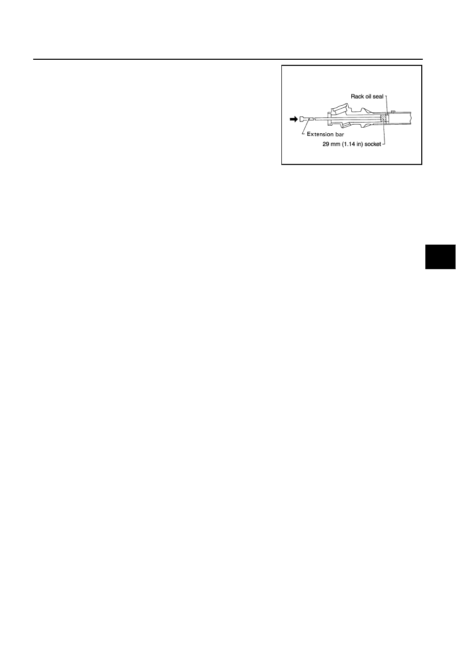
14. Push rack oil seal inside with a 29 mm (1.14 in) socket and an

extension bar to push out rack oil seal (inner side) from gear
housing assembly.

CAUTION:

Do not damage gear housing assembly and cylinder inner
wall. Gear housing assembly must be replaced if damaged
because it may cause fluid leakage.

INSPECTION AFTER DISASSEMBLY
Boot

Check boot for cracks, and replace it if a malfunction is detected.

Rack Assembly

Check rack for damage or wear, and replace it if a malfunction is detected.

Gear-Sub Assembly

Check gear-sub assembly for damage or wear, and replace it if a malfunction is detected.

Rotate gear-sub assembly and check for torque variation or rattle, and replace it if a malfunction is
detected.

Gear Housing Assembly

Check gear housing assembly for damage and scratches (inner wall). Replace if there are.

SGIA0179E

PS-24

POWER STEERING GEAR AND LINKAGE

Outer Socket and Inner Socket

1.

Ball joint swinging torque

Hook a spring balance at the point shown in the figure and
pull the spring balance. Make sure that the spring balance
reads the specified value when ball stud and inner socket
start to move. Replace outer socket and steering gear assem-
bly if they are outside the standard.

2.

Ball joint rotating torque

Make sure that the reading is within the following specified
range using the preload gauge [SST]. Replace outer socket if
the reading is outside the specified value.

3.

Ball joint axial end play

Apply an axial load of 490 N (50 kg, 111 lb) to ball stud using a
dial gauge. Measure amount of stud movement, and then
make sure that the value is within the following specified
range. Replace outer socket and inner socket if the measured
value is outside the standard.

SGIA0896E

Items

Outer socket

Inner socket

Measuring point of spring balance

Stud cotter pin mounting hole

Measuring point at *mark shown in the figure

Swinging torque

0.3 – 2.9 N·m

(0.03 – 0.29 kg-m, 3 – 25 in-lb)

1.0 – 7.8  N·m

(0.11 – 0.79 kg-m, 9.0 – 69 in-lb)

Spring balance measurement

4.81 – 45.7 N

(0.5 – 4.7 kg, 1.1 – 10.4 lb)

8.9 – 64 N

(0.9 – 6.5 kg, 2.0 – 14.3 lb)

Outer socket rotating torque

0.3 – 2.9 N·m (0.03 – 0.29 kg-m, 3 – 25 in-lb)

SGIA0941E

Outer socket

0.5 mm (0.020 in) or less

Inner socket

0.2 mm (0.008 in) or less

SGIA0057E

POWER STEERING GEAR AND LINKAGE

PS-25

C

D

E

F

H

I

J

K

L

M

A

B

PS

ASSEMBLY

1.

Apply recommended fluid to O-ring. Put an O-ring into a rack Teflon ring.

2.

Heat rack Teflon ring to approximately 40

°

C (104

°

F) with a

dryer. Assemble it to mounting groove of rack assembly.

3.

Install the Teflon ring correcting tool [SST] from tooth side of
rack to fit rack Teflon ring on rack. Compress the ring with tool.

4.

Apply recommended grease to rack oil seal, and then install
rack oil seal in the following procedure. Then assemble rack
assembly to gear housing assembly.

CAUTION:

Install rack oil seal in a direction so that the lip of inner oil
seal and the lip of outer oil seal face each other.

Do not damage retainer sliding surface by rack assembly.
Replace gear housing assembly if damaged.

Do not damage gear housing assembly inner wall by rack
assembly. Gear housing assembly must be replaced if
damaged because it may cause fluid leakage. 

a.

Wrap an OHP sheet [approximately 70 mm (2.76 in) 

×

 100 mm

(3.94 in)]. Around rack assembly teeth to avoid damaging rack
oil seal (inner). Install rack oil seal over sheet. Then, pull OHP
sheet along with rack oil seal until they pass rack assembly
teeth, and remove OHP sheet.

SGIA0153E

SGIA0154E

SGIA0205E

SGIA0155E

PS-26

POWER STEERING GEAR AND LINKAGE

b.

Insert rack oil seal (inner) into rack assembly piston (rack Teflon
ring).

c.

Push retainer to adjusting screw side by hand, and move the
rack assembly inside the gear housing assembly so that the
rack oil seal (inner) can be pressed against the gear housing
assembly.

d.

Wrap an OHP sheet [approximately 70 mm (2.76 in) 

×

 100 mm

(3.94 in)]. Around the edge to avoid damaging rack oil seal
(outer). Install rack oil seal over sheet. Then, pull oil seal along
with OHP sheet until they pass rack edge, and remove OHP
sheet. 

e.

Install end cover assembly to rack edge, and move rack oil seal
(outer) until it contacts with gear housing assembly.

5.

Tighten end cover assembly to specified torque using a 36 mm
(1.42 in) open head (suitable tool).

CAUTION:

Do not damage rack assembly. Replace it if damaged
because it may cause fluid leakage.

6.

Crimp gear housing assembly at one point using a punch as
shown in the figure so as to prevent end cover assembly from
getting loose after tightening end cover assembly.

7.

Apply recommended fluid to O-ring, and then install O-ring to
gear housing assembly.

8.

Install gear-sub assembly to gear housing assembly.

9.

Install power steering solenoid valve to gear-sub assembly.

10. Decide on the neutral position for the rack.

11. Install rear cover cap to gear sub-assembly.

CAUTION:

Make sure that the projection of rear cover cap is aligned
with the marking position of gear housing assembly.

SGIA0671E

SGIA0157E

SST081B

SGIA0871E

Drive type

2WD

AWD

Rack stroke L

68.5 mm (2.697 in)

67.0 mm (2.638 in)

SGIA0877E


Content   ..  1000  1001  1002  1003   ..