Content .. 999 1000 1001 1002 ..
Infiniti M35/M45 Y50. Manual - part 1001
POWER STEERING GEAR AND LINKAGE
PS-19
C
D
E
F
H
I
J
K
L
M
A
B
PS
POWER STEERING GEAR AND LINKAGE
PFP:49001
Removal and Installation
NGS000DC
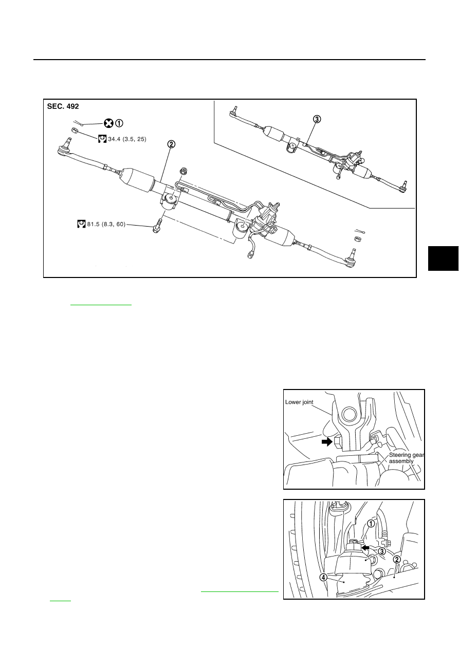
COMPONENTS
CAUTION:
Spiral cable may be cut if steering wheel turns while separating steering column assembly and steer-
ing gear assembly. Be sure to secure steering wheel using string to avoid turning.
REMOVAL
1.
Set vehicle to the straight-ahead position.
2.
Remove tires from vehicle with a power tool.
3.
Remove undercover from vehicle with a power tool.
4.
Remove lower side fixing bolt of lower joint.
5.
Remove cotter pin (1), and then loosen the nut.
6.
Remove steering outer socket (2) from steering knuckle (3) so
as not to damage ball joint boot (4) using the ball joint remover
(suitable tool).
CAUTION:
Temporarily tighten the nut to prevent damage to threads
and to prevent the ball joint remover from suddenly coming
off.
7.
Remove high and low pressure piping of hydraulic piping, and
then drain power steering fluid. Refer to
1.
Cotter pin
2.
Steering gear assembly
3.
Steering gear assembly
(AWD models)
Refer to
, for the symbols in the figure.
SGIA1387E
SGIA0844E
SGIA1183E