Infiniti M35/M45 Y50. Manual - part 1003


  Index      Infiniti     Infiniti M35/M45 Y50 - service repair manual 2007 year


Search            copyright infringement  


Content   ..  1001  1002  1003  1004   ..


Infiniti M35/M45 Y50. Manual - part 1003


POWER STEERING GEAR AND LINKAGE

PS-27

C

D

E

F

H

I

J

K

L

M

A

B

PS

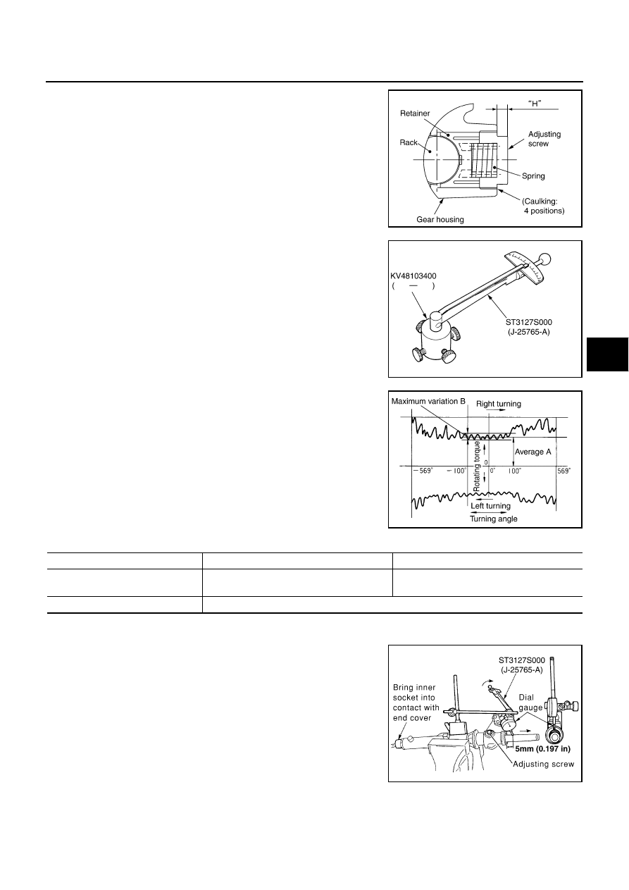
12. Apply recommended thread locking sealant to the thread (2

turns thread), and then screw in the adjusting screw until it
reaches height “H” from gear housing assembly measured
before disassembling.

13. Move rack assembly 10 strokes throughout the full stroke so that

the parts can fit with each other.

14. Measure pinion rotating torque within 

±

180

°

 of neutral position

of the rack assembly using the preload gauge [SST] and preload
adapter [SST]. Stop the gear at the point where highest torque is
read.

15. Loosen adjusting screw and retighten to 5.4 N·m (0.55 kg-m, 48

in-lb), and then loosen by 20 to 40

°

.

16. Measure pinion rotating torque using the preload adapter [SST]

and preload gauge [SST] to make sure that the measured value
is within the standard. Readjust if the value is outside the stan-
dard. Replace steering gear assembly if the value is outside the
standard after readjusting or adjusting screw rotating torque is 5
N·m (0.51 kg-m, 44 in-lb) or less.

17. Apply recommended liquid gasket to inner socket and turn pinion fully to left with inner socket installed to

gear housing assembly.

18. Set dial gauge as shown in the figure. Measure vertical move-

ment of rack assembly when pinion is turned clockwise with
torque of 19.6 N·m (2.0 kg-m, 14 ft-lb). Readjust adjusting screw
angle if the measured value is outside the standard. Replace
steering gear assembly if the measured value is still outside the
standard or adjusting screw rotating torque is 5 N·m (0.51 kg-m,
44 in-lb) or less.

SGIA0624E

SGIA0942E

SGIA0936E

Pinion rotating torque standard

2WD

AWD

Around neutral position (within

±

100

°

Average A

1.95 - 2.58 N·m

(0.20 - 0.26 kg-m, 18 - 22 in-lb)

2.27 - 3.05 N·m

(0.24 - 0.31 kg-m, 20 - 26 in-lb)

Maximum variation B

0.98 N·m (0.10 kg-m, 9.0 in-lb)

SGIA1185E

PS-28

POWER STEERING GEAR AND LINKAGE

19. Install large end of boot to gear housing assembly.

20. Install small end of boot to inner socket boot mounting groove.

21. Install boot clamp to boot small end.

22. Install large side of boot clamp.

Tighten large side of boot with boot clamp (stainless wire).

Wrap clamp around boot groove for two turns. Insert a flat-
bladed screwdriver in loops on both ends of wire. Twist 4 to
4.5 turns while pulling them with force of approximately 98 N
(10 kg, 22 lb).

Twist boot clamp as shown. Pay attention to relationship
between winding and twisting directions.

Twisted point of clamp is in the opposite side of adjusting
screw (1) as shown in the figure (to prevent contact with other
parts). 

Measuring point

Rack axial direction

5 mm (0.20 in) from housing end surface

Rack radial direction

Axial direction of the adjusting screw

Vertical movement of rack

0.265 mm (0.0104 in)

SGIA1325E

Wire length L

: 370 mm (14.57 in)

SGIA0163E

SGIA0164E

SGIA1186E

POWER STEERING GEAR AND LINKAGE

PS-29

C

D

E

F

H

I

J

K

L

M

A

B

PS

Bent cut end of the wire toward rack axial as shown in the fig-
ure after twisting the wire 4 to 4.5 turns so that cut end does
not contact with boot.

CAUTION:

Keep gap from cylinder tube 5 mm (0.20 in) or more.

23. Install cylinder tubes to gear housing assembly.

24. Adjust inner socket to standard length L, and then tighten lock

nut to the specified torque. Refer to 

PS-21, "COMPONENTS"

 .

Check length of inner socket L again after tightening lock nut.
Make sure that the length is the standard.

CAUTION:

Adjust toe-in after this procedure. Length achieved after
toe-in adjustment is not necessary the above value.

SGIA0260J

Drive type

2WD

AWD

Inner socket length L

63.9 mm (2.516 in)

55.2 mm (2.173 in)

SGIA0167E

PS-30

POWER STEERING OIL PUMP

POWER STEERING OIL PUMP

PFP:49110

On-Vehicle Inspection and Service

NGS000DE

CHECKING RELIEF OIL PRESSURE

CAUTION:

Make sure that belt tension is normal before starting the following procedure.

1.

Connect the hydraulic pressure gauge [SST] between oil pump
discharge connector and high-pressure hose. Bleed air from the
hydraulic circuit while opening valve fully. Refer to 

PS-8, "Air

Bleeding Hydraulic System"

 .

2.

Start engine. Run engine until oil temperature reaches 50 to
80

°

C (122 to 176

°

F).

CAUTION:

Leave the valve of the hydraulic pressure gauge [SST]
fully open while starting and running engine. If engine is
started with the valve closed, the hydraulic pressure in
oil pump goes up to the relief pressure along with
unusual increase of oil temperature.

Be sure to keep hose clear of belts and other parts when
engine is started.

3.

Fully close the hydraulic pressure gauge [SST] valve with
engine at idle and measure the relief oil pressure.

CAUTION:

Never keep valve closed for 10 seconds or longer.

4.

Open the valve slowly after measuring. Repair oil pump if the
relief oil pressure is outside the standard. Refer to 

PS-31, "Dis-

assembly and Assembly (Models with VK45DE)"

 , 

PS-35, "Disassembly and Assembly (Models with

VQ35DE)"

 .

5.

After inspection, disconnect the hydraulic pressure gauge [SST] from hydraulic circuit, then add fluid and
bleed air. Refer to 

PS-8, "Air Bleeding Hydraulic System"

 .

Removal and Installation

NGS000DF

REMOVAL

1.

Drain power steering fluid from reservoir tank.

2.

Remove undercover from vehicle with a power tool.

3.

Loosen drive belt. Refer to 

EM-16, "DRIVE BELTS"

  (VQ35DE), 

EM-174, "DRIVE BELTS"

  (VK45DE).

4.

Remove drive belt from oil pump pulley.

5.

Remove piping of high pressure and low pressure (drain fluid from their pipings). Refer to 

PS-39,

"HYDRAULIC LINE"

 .

6.

Remove power steering oil pump mounting bolts, and then remove power steering oil pump. Refer to 

PS-

39, "Removal and Installation"

 .

INSTALLATION

Installation is the reverse order of removal. For tightening torque, refer to 

PS-39, "HYDRAULIC LINE"

 .

Perform the following procedure after installing.

Adjust belt tension (VQ35DE). Refer to 

EM-16, "Tension Adjustment"

 .

About the installation of VK45DE drive belt, refer to 

EM-174, "Tension Adjustment"

 .

Bleed air. Refer to 

PS-8, "Air Bleeding Hydraulic System"

 .

Relief oil pressure:

8,520 - 9,320 kpa (86.9 - 95.1 kg/cm

2

 , 1,235 - 1,351 psi)

SGIA0915E


Content   ..  1001  1002  1003  1004   ..