Infiniti I35 (A33). Manual - part 605


  Index      Infiniti     Infiniti I35 (A33) - service repair manual 2004 year


Search            


Content   ..  603  604  605  606   ..


Infiniti I35 (A33). Manual - part 605


SMA525A

On-vehicle Service

REAR SUSPENSION PARTS

NHSU0029

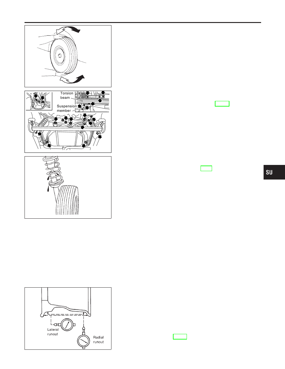
Check axle and suspension parts for excessive play, wear or dam-
age.

I

Shake each rear wheel to check for excessive play.

SSU014

I

Retighten all nuts and bolts to the specified torque.

Tightening torque:

Refer to “REAR SUSPENSION”, SU-18.

SMA113

I

Check shock absorber for oil leakage or other damage.

I

Check wheelarch height. Refer to “On-vehicle Service”,
“FRONT SUSPENSION PARTS”, SU-6.

REAR WHEEL ALIGNMENT

NHSU0030

Before checking rear wheel alignment, be sure to make a prelimi-
nary inspection (Unladen*).
*: Fuel, radiator coolant and engine oil full. Spare tire, jack, hand
tools and mats in designated positions.

SFA975B

Preliminary Inspection

NHSU0030S01

1.

Check tires for wear and improper inflation.

2.

Check wheels for deformation, cracks and other damage. If
deformed, remove wheel and check wheel runout.

a.

Remove tire from wheel and mount wheel on a tire balance
machine.

b.

Set dial indicator as shown in the illustration.

Wheel runout (Dial indicator value):

Refer to SDS, SU-16.

3.

Check front wheel bearings for looseness.

GI

MA

EM

LC

EC

FE

AT

AX

BR

ST

RS

BT

HA

SC

EL

IDX

REAR SUSPENSION

On-vehicle Service

SU-19

4.

Check front suspension for looseness.

5.

Check steering linkage for looseness.

6.

Check that front shock absorbers work properly.

7.

Check vehicle posture (Unladen).

SFA948A

Camber

NHSU0030S02

Camber is preset at factory and cannot be adjusted.

Camber:

Refer to SDS, SU-26.

I

If the camber is not within specification, inspect and replace
any damaged or worn rear suspension parts.

SFA614B

SFA234AC

Toe-in

NHSU0030S03

Toe-in is preset at factory and cannot be adjusted.
Measure

toe-in

using

following

procedure.

If

out

of

specification, inspect and replace any damaged or worn rear
suspension parts.

WARNING:

I

Perform following procedure always on a flat surface.

I

Make sure that no person is in front of the vehicle before
pushing it.

1.

Bounce rear of vehicle up and down to stabilize the posture.

2.

Push the vehicle straight ahead about 5 m (16 ft).

3.

Put a mark on base line of the tread (rear side) of both tires at
the same height of hub center. This mark is a measuring point.

4.

Measure distance “A” (rear side).

5.

Push the vehicle slowly ahead to rotate the wheels 180
degrees (1/2 turn).

If the wheels have rotated more than 180 degrees (1/2 turn), try
the above procedure again from the beginning. Never push
vehicle backward.
6.

Measure distance “B” (front side).

Total toe-in: A − B

Refer to SDS, SU-26.

REAR SUSPENSION

On-vehicle Service (Cont’d)

SU-20

Removal and Installation

NHSU0031

SSU015

1.

Washer

2.

Bushing

3.

Shock absorber mounting seal

4.

Shock absorber mounting bracket

5.

Distance tube

6.

Bushing

7.

Bound bumper cover

8.

Bound bumper

9.

Coil spring

10. Shock absorber

11. Torsion beam
12. Control rod
13. Lateral link
14. ABS sensor
15. Suspension member

GI

MA

EM

LC

EC

FE

AT

AX

BR

ST

RS

BT

HA

SC

EL

IDX

REAR SUSPENSION

Removal and Installation

SU-21

SSU016

SSU017

REMOVAL

NHSU0031S01

CAUTION:

I

Before removing the rear suspension assembly, discon-
nect the ABS wheel sensor from the assembly. Failure to
do so may result in damage to the sensor wires and the
sensor becoming inoperative.

I

Remove suspension assembly.

1.

Remove tires, then remove brake hose lock plate.

2.

Disconnect parking brake cable from caliper and remove brake
caliper and rotor.

Suspend caliper assembly with wire so as not to stretch brake
hose.
Be careful not to depress brake pedal, or piston will pop out.
Make sure brake hose is not twisted.
3.

Using a transmission jack, raise torsion beam a little, and
remove nuts and bolts from the trailing arm, shock absorber
assembly (lower side) and lateral link.

4.

Lower transmission jack, and remove suspension.

5.

Remove trunk room trim. Refer to BT-43, “Trunk Room Trim”.

6.

Remove strut securing nuts (upper side). Then pull out strut
assembly.

SSU020

INSTALLATION

NHSU0031S02

I

Install suspension assembly.

CAUTION:

Refill with new brake fluid “DOT 3”.
Never reuse drained brake fluid.
1.

Install suspension member.

a.

Temporarily tighten bolt 5.

b.

Tighten all bolts in numerical order shown in the figure.

Tightening torque:

Refer to SU-21.

SSU018

2.

Attach control rod to lateral link. Do not tighten bolts at this
time.

3.

Attach lateral link, control rod and torsion beam to vehicle. Do
not tighten bolts at this time.

REAR SUSPENSION

Removal and Installation (Cont’d)

SU-22


Content   ..  603  604  605  606   ..