Infiniti I35 (A33). Manual - part 606
SSU019
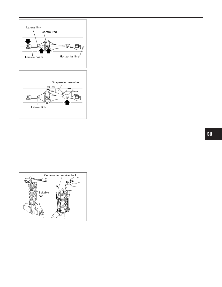
4.
Using a transmission jack to lift the torsion beam, place lateral
link and control rod horizontally against torsion beam. Tighten
bolts and nuts to specified torque.
SSU021
5.
Tighten lateral link at suspension member.
6.
Attach shock absorber assembly to vehicle. Then tighten the
upper side of shock absorber assembly.
7.
Remove transmission jack and lower torsion beam so that the
shock absorber assembly reaches full extension. Tighten tor-
sion beam and lower side of shock absorber assembly to
specified torque.
Coil Spring and Shock Absorber
REMOVAL AND INSTALLATION
NHSU0032
Remove shock absorber upper and lower fixing nuts.
Do not remove piston rod lock nut on vehicle.
SRA806A
DISASSEMBLY
NHSU0033
1.
Set shock absorber in vise, then loosen piston rod lock nut.
Do not remove piston rod lock nut at this time.
2.
Compress spring with Tool so that the shock absorber upper
spring seat can be turned by hand.
WARNING:
Make sure that the pawls of the two spring compressors are
firmly hooked on the spring. The spring compressors must be
tightened alternately so as not to tilt the spring.
3.
Remove piston rod lock nut.
INSPECTION
NHSU0034
Shock Absorber Assembly
NHSU0034S01
I
Check for smooth operation through a full stroke, both com-
pression and extension.
I
Check for oil leakage on welded or gland packing portions.
I
Check piston rod for cracks, deformation or other damage.
Replace if necessary.
Upper Rubber Seat and Bushing
NHSU0034S02
Check rubber parts for deterioration or cracks.
Replace if necessary.
GI
MA
EM
LC
EC
FE
AT
AX
BR
ST
RS
BT
HA
SC
EL
IDX
REAR SUSPENSION
Removal and Installation (Cont’d)
SU-23