Infiniti I35 (A33). Manual - part 602


  Index      Infiniti     Infiniti I35 (A33) - service repair manual 2004 year


Search            


Content   ..  600  601  602  603   ..


Infiniti I35 (A33). Manual - part 602


SFA975B

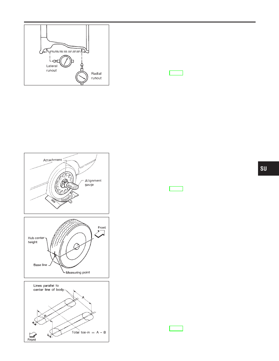
Preliminary Inspection

NHSU0007S01

1.

Check tires for wear and improper inflation.

2.

Check wheels for deformation, cracks and other damage.
If deformed, remove wheel and check wheel runout.

a.

Remove tire from wheel and mount wheel on a tire balance
machine.

b.

Set dial indicator as shown in the illustration.

Wheel runout (Dial indicator value):

Refer to SDS, SU-16.

3.

Check front wheel bearings for looseness.

4.

Check front suspension for looseness.

5.

Check steering linkage for looseness.

6.

Check that front shock absorbers work properly.

7.

Check vehicle posture (Unladen).

SRA096A

Camber, Caster and Kingpin Inclination

NHSU0007S02

Camber, caster and kingpin inclination are preset at factory
and cannot be adjusted.
1.

Measure camber, caster and kingpin inclination of both right
and left wheels with a suitable alignment gauge.

Camber, caster and kingpin inclination:

Refer to SDS, SU-15.

2.

If

camber,

caster

or

kingpin

inclination

is

not

within

specification, inspect front suspension parts. Replace dam-
aged or worn out parts.

AFA050

Toe-in

NHSU0007S03

Measure toe-in using the following procedure.

WARNING:

I

Always perform the following procedure on a flat surface.

I

Make sure that no person is in front of the vehicle before
pushing it.

1.

Bounce front of vehicle up and down to stabilize the posture.

2.

Push the vehicle straight ahead about 5 m (16 ft).

3.

Put a mark on base line of tread (rear side) of both tires at the
same height as hub center. These are measuring points.

SFA234AC

4.

Measure distance “A” (rear side).

5.

Push the vehicle slowly ahead to rotate the wheels 180
degrees (1/2 turn).

If the wheels have rotated more than 180 degrees (1/2 turn), try
the above procedure again from the beginning. Never push
vehicle backward.
6.

Measure distance “B” (front side).

Total toe-in:

Refer to SDS, SU-15.

GI

MA

EM

LC

EC

FE

AT

AX

BR

ST

RS

BT

HA

SC

EL

IDX

FRONT SUSPENSION

On-vehicle Service (Cont’d)

SU-7

SFA486A

7.

Adjust toe-in by varying the length of steering tie-rods.

a.

Loosen lock nuts.

b.

Adjust toe-in by screwing tie-rods in and out.

Standard length “L”:

Refer to ST-30, “SDS”.

c.

Tighten lock nuts to specified torque.

Lock nut tightening torque:

Refer to ST-15, “POWER STEERING GEAR AND LINK-
AGE”.

SFA439BA

Front Wheel Turning Angle

NHSU0007S04

1.

Set wheels in straight-ahead position. Then move vehicle for-
ward until front wheels rest on turning radius gauge properly.

2.

Rotate steering wheel all the way right and left; measure turn-
ing angle.
Do not hold the steering wheel on full lock for more than
15 seconds.

Wheel turning angle (Full turn):

Refer to SDS, SU-15.

SSU023

3.

Check stopper bolt head to see whether it contacts stopper
bracket at specified outside wheel angle. If not, adjust stopper
bolt to contact stopper bracket at the correct angle.
Adjust protrusion of stopper bolt before placing stopper bolt
cap.
Apply grease to face of stopper bracket that bolt touches.

Tighten stopper bolt lock nut.

: 54 - 72 N·m (5.5 - 7.3 kg-m, 40 - 53 ft-lb)

FRONT SUSPENSION

On-vehicle Service (Cont’d)

SU-8

Coil Spring and Shock Absorber

COMPONENTS

=NHSU0008

SSU056

1.

Strut spacer

2.

Strut mount insulator

3.

Strut mount bracket

4.

Strut mount bearing

5.

Spring upper seat

6.

Spring rubber seat

7.

Bound bumper rubber

8.

Coil spring

9.

Shock absorber

10. Suspension member
11. Rebound stopper
12. Wheel hub and steering knuckle
13. Cotter pin

14. Bush link pin
15. Transverse link
16. Stabilizer
17. Connecting rod
18. Stabilizer clamp
19. Bushing

GI

MA

EM

LC

EC

FE

AT

AX

BR

ST

RS

BT

HA

SC

EL

IDX

FRONT SUSPENSION

Coil Spring and Shock Absorber

SU-9

SFA956A

REMOVAL AND INSTALLATION

=NHSU0009

I

Remove shock absorber fixing bolt and nut (to hoodledge).

I

Do not remove piston rod lock nut on vehicle.

SSU002

DISASSEMBLY

NHSU0010

1.

Set shock absorber on vise, then loosen piston rod lock nut.

I

Do not remove piston rod lock nut at this time.

2.

Compress spring with Tool so that shock absorber mounting
insulator can be turned by hand.

WARNING:

Make sure that the pawls of the two spring compressors are
firmly hooked on the spring. The spring compressors must be
tightened alternately so as not to tilt the spring.

SSU003

3.

Remove piston rod lock nut.

INSPECTION

NHSU0011

Shock Absorber Assembly

NHSU0011S01

I

Check for smooth operation through a full stroke, both com-
pression and extension.

I

Check for oil leakage on welded or gland packing portions.

I

Check piston rod for cracks, deformation or other damage.
Replace if necessary.

Mounting Insulator and Rubber Parts

NHSU0011S02

I

Check cemented rubber-to-metal portion for separation or
cracks. Check rubber parts for deterioration.
Replace if necessary.

Thrust Bearing

NHSU0011S06

I

Check thrust bearing parts for abnormal noise or excessive
rattle in axial direction.

I

Replace if necessary.

Coil Spring

NHSU0011S03

I

Check for cracks, deformation or other damage. Replace if
necessary.

FRONT SUSPENSION

Coil Spring and Shock Absorber (Cont’d)

SU-10


Content   ..  600  601  602  603   ..