Infiniti I35 (A33). Manual - part 573
SRS903-B
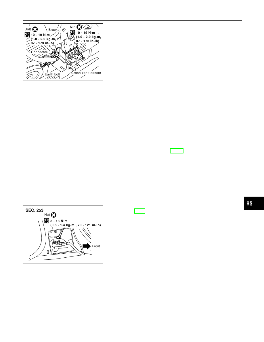
1.
Disconnect crash zone connector.
2.
Remove earth bolt and remove nuts from crash zone sensor.
Then remove the crash zone sensor from bracket.
NOTE:
I
To install, reverse the removal procedure sequence.
Satellite Sensor
REMOVAL AND INSTALLATION
NHRS0014
CAUTION:
I
Before servicing SRS, turn the ignition switch off, discon-
nect both battery cables and wait at least 3 minutes.
I
Do not use old nuts after removal; replace with new ones.
I
Check satellite sensor for proper installation.
I
Check satellite sensor to ensure they are free of
deformities, dents, cracks or rust. If it shows any visible
signs of damage, replace it with new one.
I
After replacement of satellite sensor, check SRS function
and perform self-diagnosis for SRS. Refer to “SRS Opera-
tion Check” for details. (RS-41)
I
Do not attempt to disassemble satellite sensor.
I
Replace satellite sensor if it has been dropped or sus-
tained an impact.
SRS979
1.
Remove seat belt pre-tensioner. Refer to “Front Seat Belt” for
details. (RS-4)
2.
Disconnect satellite sensor connector.
3.
Remove bolt and nuts from satellite sensor unit.
Then remove the satellite sensor.
NOTE:
I
To install, reverse the removal procedure sequence.
GI
MA
EM
LC
EC
FE
AT
AX
SU
BR
ST
BT
HA
SC
EL
IDX
SUPPLEMENTAL RESTRAINT SYSTEM (SRS)
Crash Zone Sensor (Cont’d)
RS-19