Infiniti I35 (A33). Manual - part 546
Temperature °C (°F)
Resistance k
Ω
35 (95)
1.51
40 (104)
1.27
45 (113)
1.07
If NG, replace ambient sensor.
RHA412H
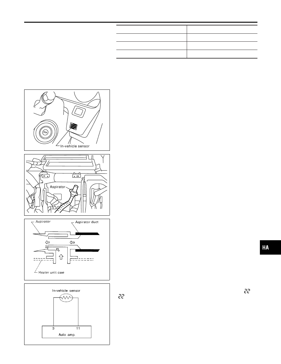
In-vehicle Sensor Circuit
COMPONENT DESCRIPTION
NHHA0218
In-vehicle sensor
NHHA0218S01
The in-vehicle sensor is located on instrument lower panel. It con-
verts variations in temperature of compartment air drawn from the
aspirator into a resistance value. It is then input into the auto
amplifier.
RHA413H
RHA482A
Aspirator
NHHA0218S02
The aspirator is located in front of heater unit. It produces vacuum
pressure due to air discharged from the heater unit, continuously
taking compartment air in the aspirator.
RHA056GB
DIAGNOSTIC PROCEDURE
NHHA0219
SYMPTOM: In-vehicle sensor circuit is open or shorted. (
or
−
is indicated on the display as a result of conducting Self-
diagnosis STEP-2.)
GI
MA
EM
LC
EC
FE
AT
AX
SU
BR
ST
RS
BT
SC
EL
IDX
TROUBLE DIAGNOSES
Ambient Sensor Circuit (Cont’d)
HA-97