Infiniti I35 (A33). Manual - part 545


  Index      Infiniti     Infiniti I35 (A33) - service repair manual 2004 year


Search            


Content   ..  543  544  545  546   ..


Infiniti I35 (A33). Manual - part 545


ECON (ECONOMY) Mode

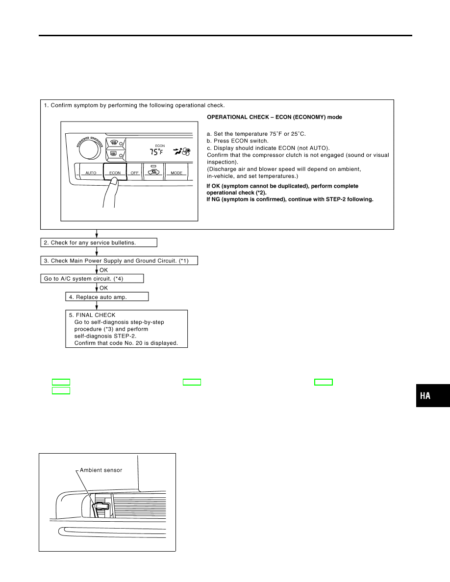
TROUBLE DIAGNOSIS PROCEDURE FOR ECON (ECONOMY) MODE

=NHHA0213

SYMPTOM:

I

ECON mode does not operate.

INSPECTION FLOW

SHA611FA

*1: HA-51
*2: HA-47

*3: HA-37

*4: HA-51

RHA410H

Ambient Sensor Circuit

COMPONENT DESCRIPTION

NHHA0214

The ambient sensor is attached in front of the right side condenser.
It detects ambient temperature and converts it into a resistance
value which is then input into the auto amplifier.

GI

MA

EM

LC

EC

FE

AT

AX

SU

BR

ST

RS

BT

SC

EL

IDX

TROUBLE DIAGNOSES

ECON (ECONOMY) Mode

HA-93

AMBIENT TEMPERATURE INPUT PROCESS

NHHA0215

The automatic amplifier includes a “processing circuit” for the ambi-
ent sensor input. However, when the temperature detected by the
ambient sensor increases quickly, the processing circuit retards the
auto amp. function. It only allows the auto amp. to recognize an
ambient temperature increase of 0.33°C (0.6°F) per 100 seconds.
As an example, consider stopping for a cup of coffee after high
speed driving. Although the actual ambient temperature has not
changed, the temperature detected by the ambient sensor will
increase. This is because the heat from the engine compartment
can radiate to the front grille area, location of the ambient sensor.

RHA051GA

DIAGNOSTIC PROCEDURE

NHHA0216

SYMPTOM: Ambient sensor circuit is open or shorted. (

or

is indicated on the display as a result of conducting Self-

diagnosis STEP-2.)

1

CHECK VOLTAGE BETWEEN AMBIENT SENSOR HARNESS CONNECTOR AND GROUND

Disconnect ambient sensor harness connector.
Do approx. 5 volts exist between ambient sensor harness connector E55 terminal No. 1 and ground?

RHA052GG

Yes or No

Yes

©

GO TO 2.

No

©

GO TO 4.

TROUBLE DIAGNOSES

Ambient Sensor Circuit (Cont’d)

HA-94

2

CHECK AMBIENT SENSOR CIRCUIT BETWEEN AMBIENT SENSOR AND AUTO AMP.

1. Disconnect auto amp. harness connector.
2. Check circuit continuity between ambient sensor harness connector E55 terminal No. 2 and auto amp. harness connec-

tor M59 terminal No. 11.

RHA475GF

Continuity should exist.

If OK, check harness for short.

OK or NG

OK

©

GO TO 3.

NG

©

Repair harness or connector.

3

CHECK AMBIENT SENSOR

Refer to HA-96.

OK or NG

OK

©

1. Replace auto amp.
2. Go to “FUNCTION CONFIRMATION PROCEDURE”, “Self-diagnosis”, HA-37 and per-

form self-diagnosis STEP-2.
Confirm that code No. 20 is displayed.

NG

©

Replace ambient sensor.

GI

MA

EM

LC

EC

FE

AT

AX

SU

BR

ST

RS

BT

SC

EL

IDX

TROUBLE DIAGNOSES

Ambient Sensor Circuit (Cont’d)

HA-95

4

CHECK AMBIENT SENSOR CIRCUIT BETWEEN AMBIENT SENSOR AND AUTO AMP.

1. Disconnect auto amp. harness connector.
2. Check circuit continuity between ambient sensor harness connector E55 terminal No. 1 and auto amp. harness connec-

tor M59 terminal No. 2.

SHA374FB

Continuity should exist.

If OK, check harness for short.

OK or NG

OK

©

1. Replace auto amp.
2. Go to “FUNCTION CONFIRMATION PROCEDURE”, “Self-diagnosis”, HA-37 and per-

form self-diagnosis STEP-2.
Confirm that code No. 20 is displayed.

NG

©

Repair harness or connector.

RHA411H

COMPONENT INSPECTION

NHHA0217

Ambient Sensor

NHHA0217S01

After disconnecting ambient sensor harness connector, measure
resistance between terminals 2 and 1 at sensor harness side, using
the table below.

Temperature °C (°F)

Resistance k

−15 (5)

12.73

−10 (14)

9.92

−5 (23)

7.80

0 (32)

6.19

5 (41)

4.95

10 (50)

3.99

15 (59)

3.24

20 (68)

2.65

25 (77)

2.19

30 (86)

1.81

TROUBLE DIAGNOSES

Ambient Sensor Circuit (Cont’d)

HA-96


Content   ..  543  544  545  546   ..