Infiniti I35 (A33). Manual - part 423


  Index      Infiniti     Infiniti I35 (A33) - service repair manual 2004 year


Search            


Content   ..  421  422  423  424   ..


Infiniti I35 (A33). Manual - part 423


FRONT DOOR KEY CYLINDER SWITCH CHECK

=NHEL0193S06

1

CHECK DOOR KEY CYLINDER SWITCH INPUT SIGNAL (LOCK/UNLOCK SIGNAL)
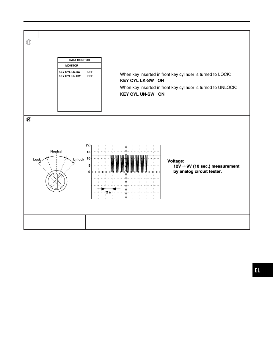
With CONSULT-II

Check front door key cylinder switch (“KEY CYL LK-SW”/“KEY CYL UN-SW”) in “DATA MONITOR” mode with CONSULT-
II.

SEL342W

Without CONSULT-II

1. Check the signal between smart entrance control unit harness connector M144 terminal 33 (L) and ground with oscillo-

scope when key inserted in front key cylinder is turned “LOCK” or “UNLOCK”.

2. Make sure signals which are shown in the figure below can be detected during 10 sec. just after key is turned “LOCK”

or “UNLOCK”.

SEL397Y

Refer to wiring diagram in EL-283.

OK or NG

OK

©

Door key cylinder switch is OK.

NG

©

GO TO 2.

GI

MA

EM

LC

EC

FE

AT

AX

SU

BR

ST

RS

BT

HA

SC

IDX

POWER DOOR LOCK

Trouble Diagnoses (Cont’d)

EL-293

2

CHECK DOOR KEY CYLINDER SWITCH

1. Disconnect door key cylinder switch harness connector.
2. Check continuity between door key cylinder switch terminals.

SEL034X

OK or NG

OK

©

Check the following.

I

Door key cylinder switch ground circuit

I

Harness for open or short between front power window main switch and door key cyl-
inder switch

If above systems are normal, replace the front power window main switch.

NG

©

Replace door key cylinder switch.

POWER DOOR LOCK

Trouble Diagnoses (Cont’d)

EL-294

DOOR LOCK ACTUATOR CHECK

=NHEL0193S08

1

CHECK DOOR LOCK ACTUATOR OPERATION

With CONSULT-II

1. Select “ACTIVE TEST” in “DOOR LOCK” with CONSULT-II.
2. Select “ALL D/LK MTR” and touch “ON”.
3. Then, select “DR D/UN MTR” and touch “ON”.
4. Select “NON DR D/UN” and touch “ON”.

SEL343W

NOTE:
If CONSULT-II is not available, skip this procedure and go to the next step.

OK or NG

OK

©

Door lock actuator is OK.

NG

©

GO TO 2.

GI

MA

EM

LC

EC

FE

AT

AX

SU

BR

ST

RS

BT

HA

SC

IDX

POWER DOOR LOCK

Trouble Diagnoses (Cont’d)

EL-295

2

CHECK DOOR LOCK ACTUATOR CIRCUIT

I

Front door lock actuator LH
Check voltage between smart entrance control unit harness connector M145 terminal 54 (GY), 55 (W/B) and ground.

SEL014Y

I

Front door lock actuator RH and rear
Check voltage between smart entrance control unit harness connector M145 terminal 54 (GY), 56 (G/Y) and ground.

SEL015Y

Refer to wiring diagram in EL-284.

OK or NG

OK

©

GO TO 3.

NG

©

Replace smart entrance control unit. (Before replacing the control unit, perform “DOOR
LOCK/UNLOCK SWITCH CHECK”.)

3

CHECK DOOR LOCK ACTUATOR

1. Disconnect door lock actuator harness connector.
2. Apply 12V direct current to door lock actuator and check operation.

SEL222W

OK or NG

OK

©

Check harness for open or short between smart entrance control unit connector and door
lock actuator.

NG

©

Replace door lock actuator.

POWER DOOR LOCK

Trouble Diagnoses (Cont’d)

EL-296


Content   ..  421  422  423  424   ..