Infiniti I35 (A33). Manual - part 413
MEL665R
GI
MA
EM
LC
EC
FE
AT
AX
SU
BR
ST
RS
BT
HA
SC
IDX
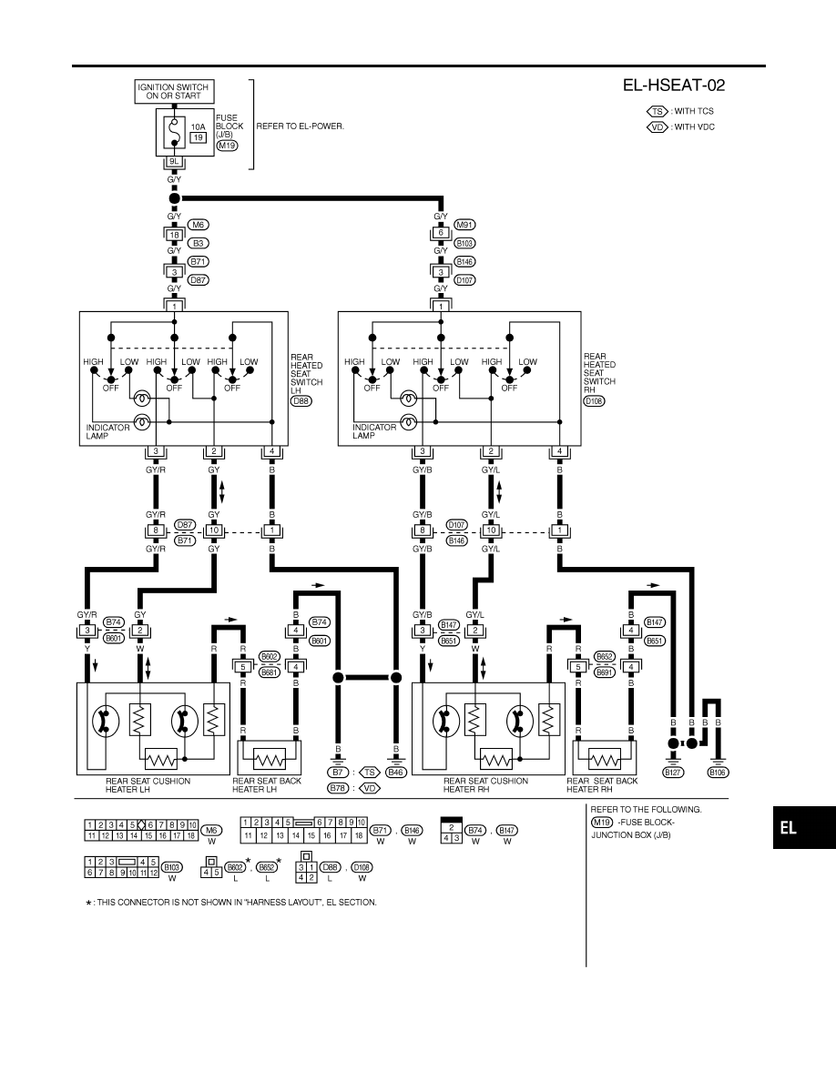
HEATED SEAT
Wiring Diagram — HSEAT — (Cont’d)
EL-253
|
|
|
MEL665R GI MA EM LC EC FE AT AX SU BR ST RS BT HA SC IDX HEATED SEAT Wiring Diagram — HSEAT — (Cont’d) EL-253 |