Infiniti I35 (A33). Manual - part 349


  Index      Infiniti     Infiniti I35 (A33) - service repair manual 2004 year


Search            


Content   ..  347  348  349  350   ..


Infiniti I35 (A33). Manual - part 349


8

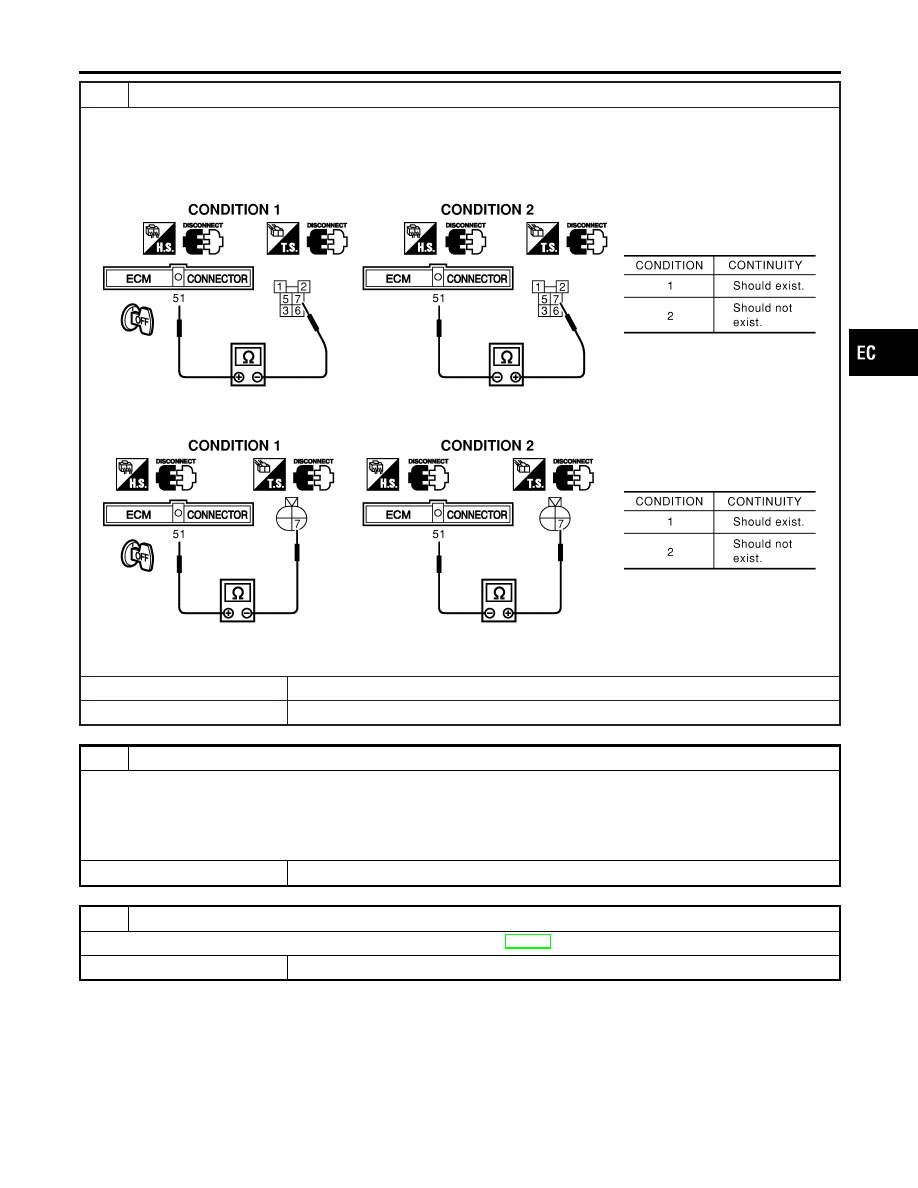
CHECK HEADLAMP INPUT SIGNAL CIRCUIT FOR OPEN OR SHORT

1. Stop engine.
2. Disconnect ECM harness connector.
3. Disconnect headlamp RH relay (Models for USA), daytime light control unit harness connector (Models for Canada).
4. Check harness continuity between ECM terminal 51 and headlamp RH relay terminal 7 under the following conditions.

(Models for USA)

SEC126D

5. Check harness continuity between ECM terminal 51 and daytime light control unit terminal 7 under the following condi-

tions.(Model for Canada)

SEC127D

6. Also check harness for short to ground and short to power.

OK or NG

OK

©

GO TO 10.

NG

©

GO TO 9.

9

DETECT MALFUNCTIONING PART

Check the following.

I

Harness connectors E81, M15

I

Harness connectors M229, F66

I

Diode E79

I

Harness for open and short between ECM and headlamp RH relay or daytime light control unit

©

Repair open circuit or short to ground or short to power in harness or connectors.

10

CHECK INTERMITTENT INCIDENT

Perform “TROUBLE DIAGNOSIS FOR INTERMITTENT INCIDENT”, EC-152.

©

INSPECTION END

GI

MA

EM

LC

FE

AT

AX

SU

BR

ST

RS

BT

HA

SC

EL

IDX

ELECTRICAL LOAD SIGNAL

Diagnostic Procedure (Cont’d)

EC-737

Wiring Diagram

NHEC0407

MEC376E

DATA LINK CONNECTORS

Wiring Diagram

EC-738

Fuel Pressure Regulator

NHEC0408

Fuel pressure at idling kPa (kg/cm

2

, psi)

Approximately 350 (3.57, 51)

Idle Speed and Ignition Timing

NHEC0409

Target idle speed

No-load* (in P or N position)

675

±

50 rpm

Air conditioner: ON

In P or N position

825 rpm or more

Ignition timing

In P or N position

15°

±

5° BTDC

*: Under the following conditions:

I

Air conditioner switch: OFF

I

Electric load: OFF (Lights, heater fan & rear window defogger)

I

Steering wheel: Kept in straight-ahead position

Mass Air Flow Sensor

NHEC0411

Supply voltage

Battery voltage (11 - 14)V

Output voltage at idle

1.1 - 1.5V*

Mass air flow (Using CONSULT-II or GST)

2.0 - 6.0

g·m/sec at idle*

7.0 - 20.0

g·m/sec at 2,500 rpm*

*: Engine is warmed up to normal operating temperature and running under no-load.

Engine Coolant Temperature Sensor

NHEC0412

Temperature °C (°F)

Resistance k

20 (68)

2.1 - 2.9

50 (122)

0.68 - 1.00

90 (194)

0.236 - 0.260

Heated Oxygen Sensor 1 Heater

NHEC0414

Resistance [at 25°C (77°F)]

3.3 - 4.0

Fuel Pump

NHEC0415

Resistance [at 25°C (77°F)]

0.2 - 5.0

Injector

NHEC0417

Resistance [at 10 - 60°C (50 - 140°F)]

13.5 - 17.3

Calculated Load Value

NHEC0420

Calculated load value % (Using CONSULT-II or GST)

At idle

10 - 35

At 2,500 rpm

10 - 35

Intake Air Temperature Sensor

NHEC0421

Temperature °C (°F)

Resistance k

25 (77)

1.9 - 2.1

Heated Oxygen Sensor 2 Heater

NHEC0422

Resistance [at 25°C (77°F)]

3.3 - 4.0

GI

MA

EM

LC

FE

AT

AX

SU

BR

ST

RS

BT

HA

SC

EL

IDX

SERVICE DATA AND SPECIFICATIONS (SDS)

Fuel Pressure Regulator

EC-739

Fuel Tank Temperature Sensor

NHEC0424

Temperature °C (°F)

Resistance k

20 (68)

2.3 - 2.7

50 (122)

0.79 - 0.90

Throttle Control Motor

NHEC1332

Resistance [at 25°C (77°F)]

Approximately 1 - 15

Crankshaft Position Sensor (POS)

NHEC1414

Refer to “Component Inspection”, EC-322.

Camshaft Position Sensor (PHASE)

NHEC0639

Refer to “Component Inspection”, EC-331.

SERVICE DATA AND SPECIFICATIONS (SDS)

Fuel Tank Temperature Sensor

EC-740


Content   ..  347  348  349  350   ..