Infiniti I35 (A33). Manual - part 107
Removal
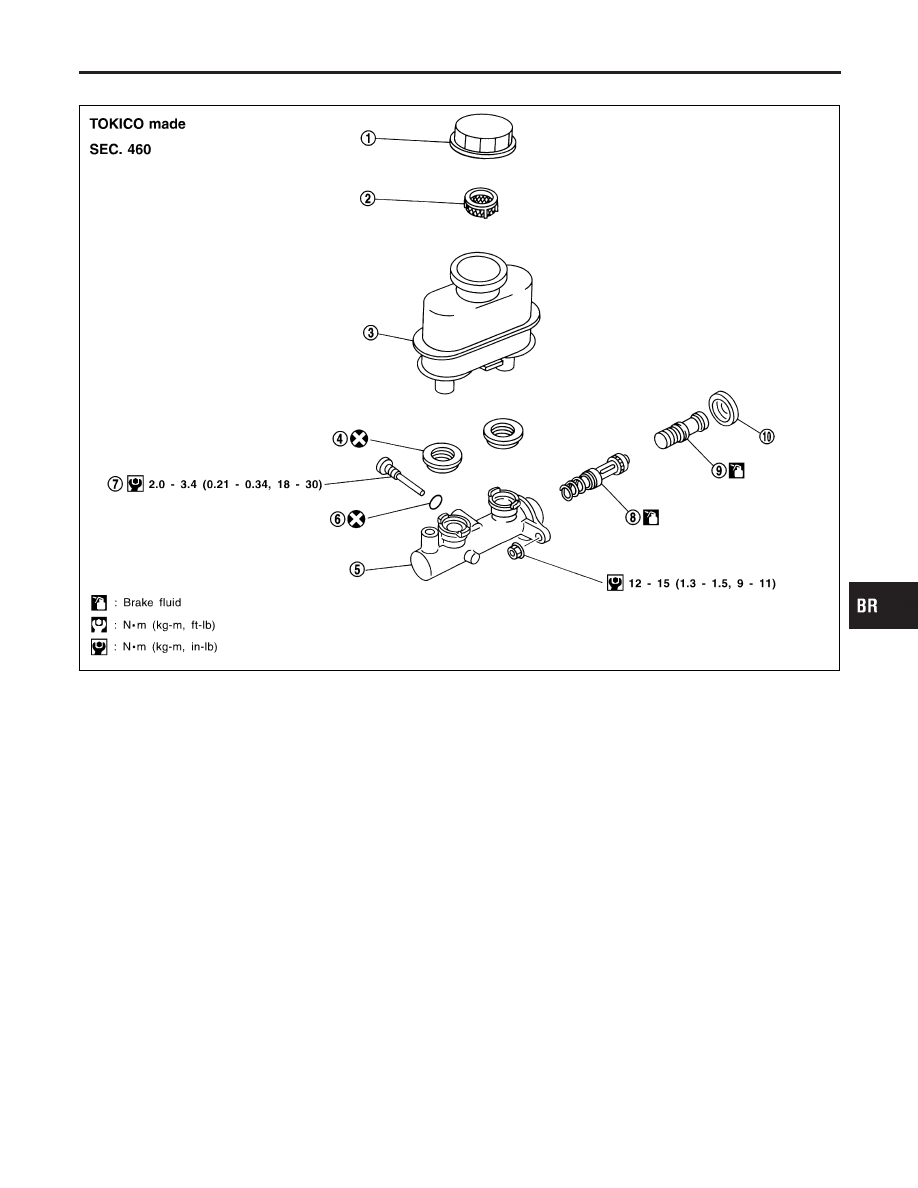
NHBR0018
SBR886E
1.
Reservoir cap
2.
Oil filter
3.
Reservoir tank
4.
Seal
5.
Cylinder body
6.
O-ring
7.
Piston stopper
8.
Secondary piston assembly
9.
Primary piston assembly
10. Stopper cap
CAUTION:
Be careful not to splash brake fluid on painted areas; it may
cause paint damage. If brake fluid is splashed on painted
areas, wash it away with water immediately.
1.
Connect a vinyl tube to bleed valve.
2.
Drain brake fluid from each bleed valve, depressing brake
pedal to empty fluid from master cylinder.
3.
Remove brake pipe flare nuts.
4.
Remove master cylinder mounting nuts.
GI
MA
EM
LC
EC
FE
AT
AX
SU
ST
RS
BT
HA
SC
EL
IDX
MASTER CYLINDER (TOKICO)
Removal
BR-13