Infiniti I35 (A33). Manual - part 72
SAT755J
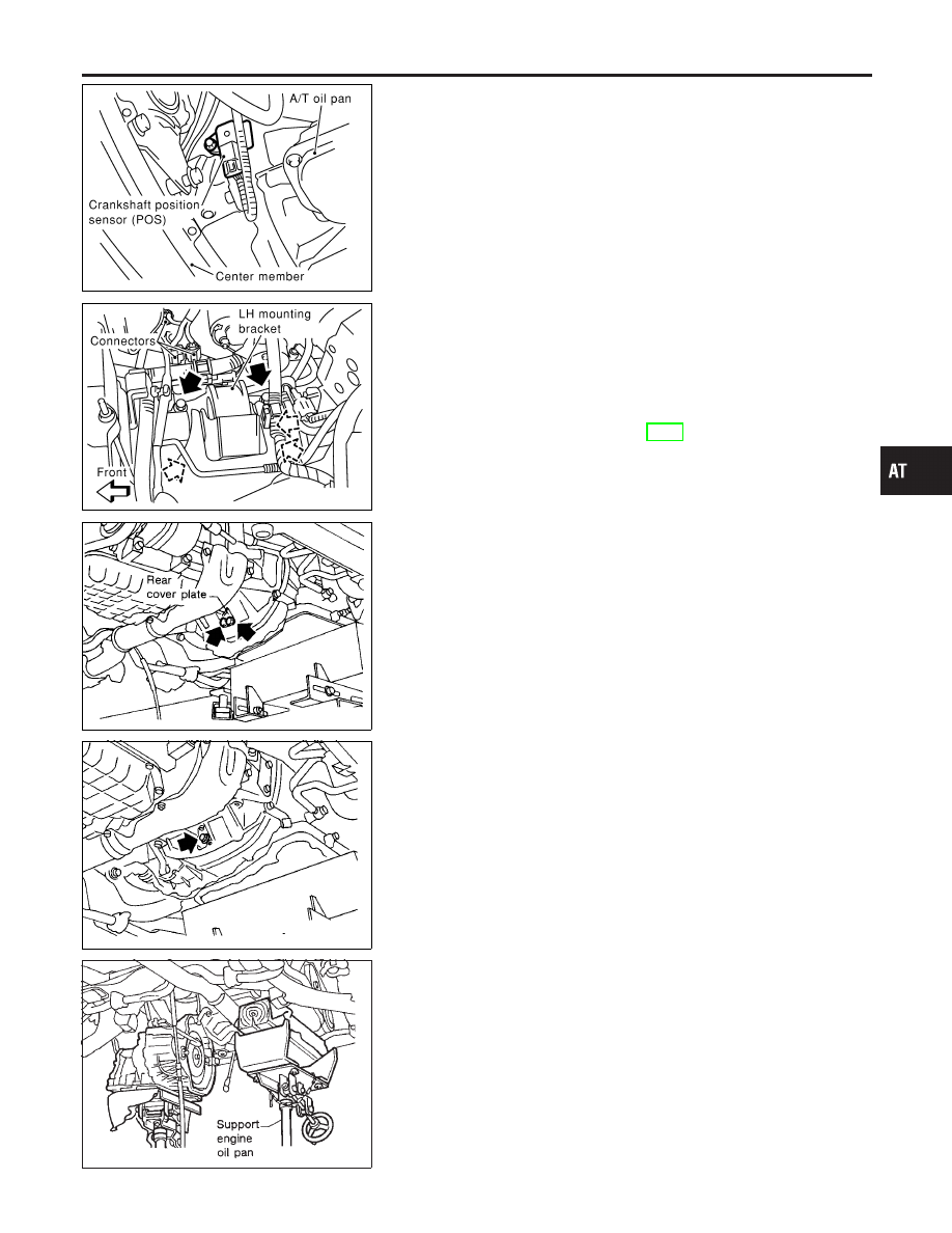
Removal
NHAT0119
SAT756J
SAT944CA
SAT615E
CAUTION:
When removing the transaxle assembly from engine, first
remove the crankshaft position sensor (POS) from the assem-
bly.
Be careful not to damage sensor edge.
1.
Remove battery and bracket.
2.
Remove air cleaner and resonator.
3.
Disconnect terminal cord assembly harness connector and
park/neutral position (PNP) switch harness connectors.
4.
Disconnect harness connectors of revolution sensor, ground
and vehicle speed sensor.
5.
Remove crankshaft position sensor (POS) from transaxle.
6.
Remove LH mounting bracket from transaxle and body.
7.
Disconnect control cable at transaxle side.
8.
Drain ATF.
9.
Remove exhaust front tube.
10. Remove drive shafts. Refer to AX-9, “Drive Shaft”.
11. Disconnect fluid cooler hoses.
12. Remove starter motor from transaxle.
13. Support engine by placing a jack under oil pan.
I
Do not place jack under oil pan drain plug.
14. Remove center member.
15. Remove rear cover plate and bolts securing torque converter
to drive plate.
I
Rotate crankshaft for access to securing bolts.
SAT947C
16. Support transaxle with a jack.
17. Remove bolts fixing A/T to engine.
18. Lower transaxle while supporting it with a jack.
GI
MA
EM
LC
EC
FE
AX
SU
BR
ST
RS
BT
HA
SC
EL
IDX
REMOVAL AND INSTALLATION
Removal
AT-285