Infiniti I35 (A33). Manual - part 71
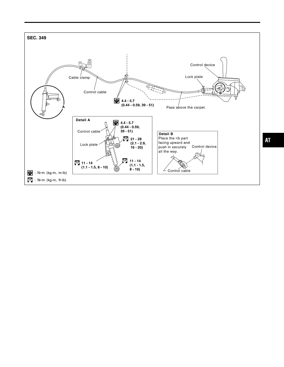
Control Cable
NHAT0263
SAT754J
GI
MA
EM
LC
EC
FE
AX
SU
BR
ST
RS
BT
HA
SC
EL
IDX
SHIFT CONTROL SYSTEM
Control Cable
AT-281
|
|
|
Control Cable NHAT0263 SAT754J GI MA EM LC EC FE AX SU BR ST RS BT HA SC EL IDX SHIFT CONTROL SYSTEM Control Cable AT-281 |