Infiniti I35 (A33). Manual - part 56
MAT491B
GI
MA
EM
LC
EC
FE
AX
SU
BR
ST
RS
BT
HA
SC
EL
IDX
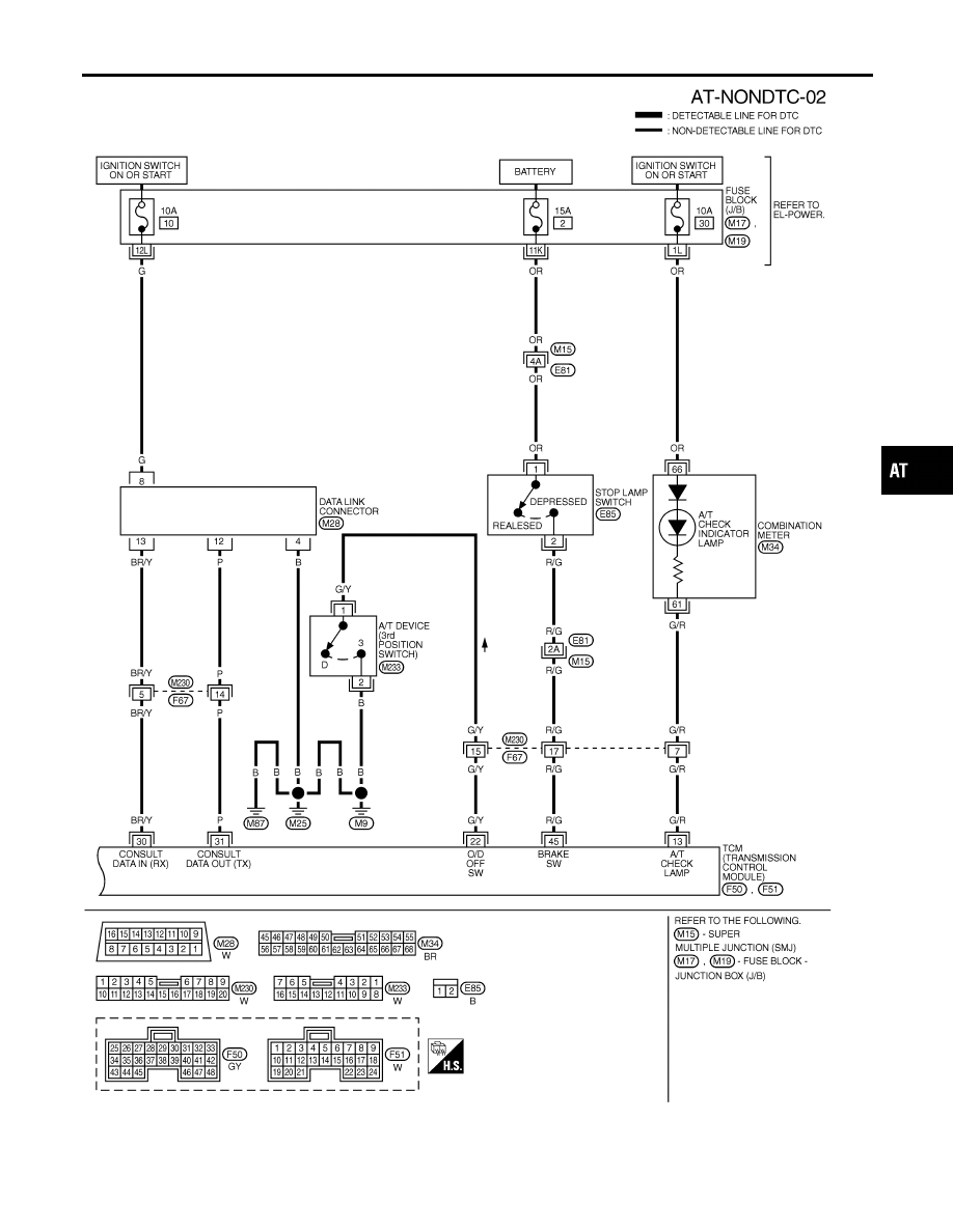
TROUBLE DIAGNOSES FOR SYMPTOMS
Wiring Diagram — AT — NONDTC (Cont’d)
AT-221
|
|
|
MAT491B GI MA EM LC EC FE AX SU BR ST RS BT HA SC EL IDX TROUBLE DIAGNOSES FOR SYMPTOMS Wiring Diagram — AT — NONDTC (Cont’d) AT-221 |