Infiniti G37 Coupe. Manual - part 542


  Index      Infiniti     Infiniti G37 Coupe - service repair manual 2008 year


Search            


Content   ..  540  541  542  543   ..


Infiniti G37 Coupe. Manual - part 542


P0555 BRAKE BOOSTER PRESSURE SENSOR

EC-349

< COMPONENT DIAGNOSIS >

[VQ37VHR]

C

D

E

F

G

H

I

J

K

L

M

A

EC

N

P

O

P0555 BRAKE BOOSTER PRESSURE SENSOR

Description

INFOID:0000000001736749

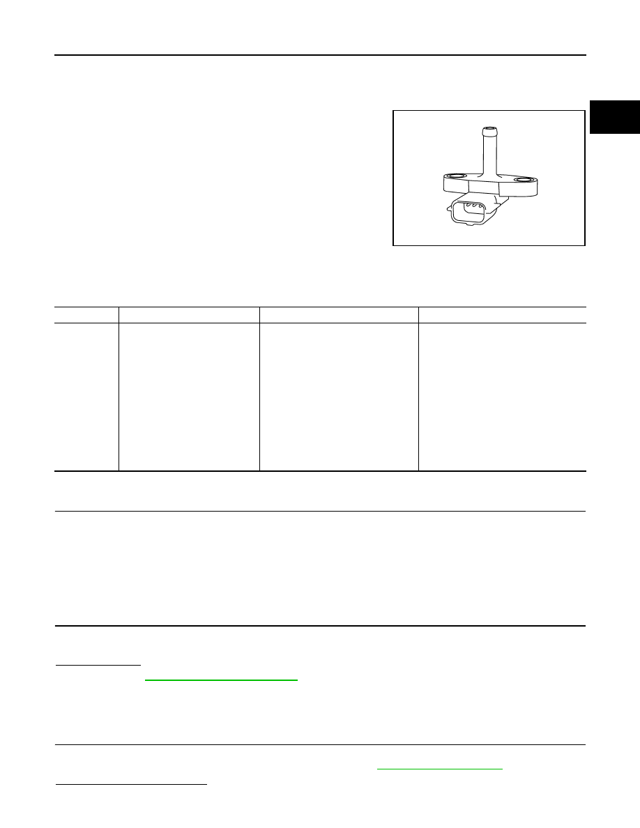
Brake booster pressure sensor is connected to brake booster by a
hose. It detects brake booster pressure and sends the voltage signal
to the ECM. The sensor uses a silicon diaphragm which is sensitive
to the change in pressure. As the pressure increases, the voltage
rises.

DTC Logic

INFOID:0000000001736751

DTC DETECTION LOGIC

DTC CONFIRMATION PROCEDURE

1.

PRECONDITIONING

If DTC Confirmation Procedure has been previously conducted, always perform the following before conduct-
ing the next test. 
1.

Turn ignition switch OFF and wait at least 10 seconds.

2.

Turn ignition switch ON.

3.

Turn ignition switch OFF and wait at least 10 seconds.

>> GO TO 2.

2.

PERFORM DTC CONFIRMATION PROCEDURE

1.

Start engine and let it idle for 10 seconds.

2.

Check DTC.

Is DTC detected?

YES

>> Go to 

EC-349, "Diagnosis Procedure"

.

NO

>> INSPECTION END

Diagnosis Procedure

INFOID:0000000001736752

1.

CHECK GROUND CONNECTION

1.

Turn ignition switch OFF.

2.

Check ground connection M95. Refer to Ground Inspection in 

GI-41, "Circuit Inspection"

.

Is the inspection result normal?

JMBIA0878ZZ

DTC No.

Trouble diagnosis name

DTC detecting condition

Possible cause

P0555

Brake booster pressure sensor 
circuit

• An excessively low voltage from the 

sensor is sent to ECM.

• An excessively high voltage from the 

sensor is sent to ECM.

• Harness or connectors

(The sensor circuit is open or shorted.)
[CKP sensor (POS) circuit is shorted.]
(APP sensor 2 circuit is shorted)
(EVAP control system pressure sensor 
circuit is shorted.)
(Refrigerant pressure sensor circuit is 
shorted.)

• Brake booster pressure sensor
• Crankshaft position sensor (POS)
• Accelerator pedal position sensor
• EVAP control system pressure sensor
• Refrigerant pressure sensor

EC-350

< COMPONENT DIAGNOSIS >

[VQ37VHR]

P0555 BRAKE BOOSTER PRESSURE SENSOR

YES

>> GO TO 2.

NO

>> Repair or replace ground connection.

2.

CHECK BRAKE BOOSTER PRESSURE SENSOR POWER SUPPLY CIRCUIT

1.

Disconnect brake booster pressure sensor harness connector.

2.

Turn ignition switch ON.

3.

Check the voltage between brake booster pressure sensor harness connector and ground.

Is the inspection result normal?

YES

>> GO TO 9.

NO

>> GO TO 3.

3.

CHECK BRAKE BOOSTER PRESSURE SENSOR POWER SUPPLY CIRCUIT-II

1.

Turn ignition switch OFF.

2.

Disconnect ECM harness connector.

3.

Check the continuity between Brake booster pressure sensor harness connector and ECM harness con-
nector.

Is the inspection result normal?

YES

>> GO TO 5.

NO

>> GO TO 4.

4.

DETECT MALFUNCTIONING PART

Check the following.
• Harness connectors F1, E3
• Harness for open between ECM and brake booster pressure sensor

>> Repair open circuit.

5.

CHECK BRAKE BOOSTER PRESSURE SENSOR POWER SUPPLY CIRCUIT-III

Check harness for short to power and short to ground, between the following terminals.

Is the inspection result normal?

YES

>> GO TO 6.

NO

>> Repair short to ground or short to power in harness or connectors. 

6.

CHECK COMPONENTS

Check the following.
• Crankshaft position sensor (POS) (Refer to 

EC-267, "Component Inspection"

.)

• EVAP control system pressure sensor (Refer to 

EC-306, "Component Inspection"

.)

Brake booster pressure sensor

Ground

Voltage

Connector

Terminal

E48

1

Ground

Approx. 5V

Brake booster pres-

sure sensor

ECM

Continuity

Connector

Terminal

Connector

Terminal

E48

1

F101

45

Existed

ECM

Sensor

Connector

Terminal

Name

Connector

Terminal

F101

45

Brake booster pressure sensor

E48

1

46

CKP sensor (POS)

F2

1

M107

103

APP sensor

E112

6

107

EVAP control system pressure sensor

B30

3

111

Refrigerant pressure sensor

E77

3

P0555 BRAKE BOOSTER PRESSURE SENSOR

EC-351

< COMPONENT DIAGNOSIS >

[VQ37VHR]

C

D

E

F

G

H

I

J

K

L

M

A

EC

N

P

O

• Refrigerant pressure sensor (Refer to 

HAC-85, "Component Function Check"

.)

Is the inspection result normal?

YES

>> GO TO 7.

NO

>> Replace malfunctioning component.

7.

CHECK APP SENSOR

Refer to 

EC-460, "Component Inspection"

.

Is the inspection result normal?

YES

>> GO TO 14.

NO

>> GO TO 8.

8.

REPLACE ACCELERATOR PEDAL ASSEMBLY

1.

Replace accelerator pedal assembly

2.

Go to 

EC-460, "Special Repair Requirement"

.

>> INSPECTION END

9.

CHECK BRAKE BOOSTER PRESSURE SENSOR GROUND CIRCUIT FOR OPEN AND SHORT

1.

Turn ignition switch OFF.

2.

Disconnect ECM harness connector.

3.

Check the continuity between brake booster pressure sensor harness connector and ECM harness con-
nector.

4.

Also check harness for short to ground and power.

Is the inspection result normal?

YES

>> GO TO 11.

NO

>> GO TO 10.

10.

DETECT MALFUNCTIONING PART

Check the following.
• Harness connectors F1, E3
• Harness for open or short between brake booster pressure sensor and ECM

>> Repair open circuit or short to ground or short to power in harness or connectors.

11.

CHECK BRAKE BOOSTER PRESSURE SENSOR INPUT SIGNAL CIRCUIT FOR OPEN AND SHORT

1.

Check the continuity between brake booster pressure sensor harness connector and ECM harness con-
nector.

2.

Also check harness for short to ground and power.

Is the inspection result normal?

YES

>> GO TO 13.

NO

>> GO TO 12.

12.

DETECT MALFUNCTIONING PART

Check the following.
• Harness connectors F1, E3
• Harness for open or short between brake booster pressure sensor and ECM

Brake booster pressure sensor

ECM

Continuity

Connector

Terminal

Connector

Terminal

E48

3

F101

36

Existed

Brake booster pressure sensor

ECM

Continuity

Connector

Terminal

Connector

Terminal

E48

2

F101

39

Existed

EC-352

< COMPONENT DIAGNOSIS >

[VQ37VHR]

P0555 BRAKE BOOSTER PRESSURE SENSOR

>> Repair open circuit or short to ground or short to power in harness or connectors.

13.

CHECK BRAKE BOOSTER PRESSURE SENSOR

Refer to 

EC-352, "Component Inspection"

.

Is the inspection result normal?

YES

>> GO TO 14.

NO

>> Replace brake booster pressure sensor.

14.

CHECK INTERMITTENT INCIDENT

Refer to 

GI-38, "Intermittent Incident"

.

>> INSPECTION END

Component Inspection

INFOID:0000000001736753

1.

CHECK BRAKE BOOSTER PRESSURE SENSOR-I

1.

Turn ignition switch OFF.

2.

Start engine and warm it up to normal operating temperature.

3.

Turn ignition switch OFF, wait at least 5 seconds and then turn ON.

4.

Check the voltage between ECM harness connector terminals as follows.

NOTE:
• To avoid the influence of intake manifold vacuum, check the voltage 1 or more minutes past after engine

is stopped.

• Because the sensor is absolute pressure sensor, output value may differ depends on atmospheric pres-

sure and altitude.

5.

Measure the atmospheric pressure.
NOTE:
As the atmospheric pressure described on the synoptic chart is the value at sea level, compensate the
pressure with the following chart.

6.

Check the manifold absolute pressure sensor value corresponding to the atmospheric pressure.

ECM

Connector

+

Terminal

Terminal

F101

39

36

Altitude

Compensated pressure

0m

0hPa

200m

-24hPa

400m

-47hPa

600m

-70hPa

800m

-92hPa

1000m

-114hPa

1500m

-168hPa

2000m

-218hPa


Content   ..  540  541  542  543   ..