Infiniti G35 (V35) Sedan. Manual - part 1270


  Index      Infiniti     Infiniti G35 (V35) Sedan - service repair manual 2007 year


Search            


Content   ..  1268  1269  1270  1271   ..


Infiniti G35 (V35) Sedan. Manual - part 1270


ST-30

< ON-VEHICLE REPAIR >

STEERING GEAR AND LINKAGE

8.

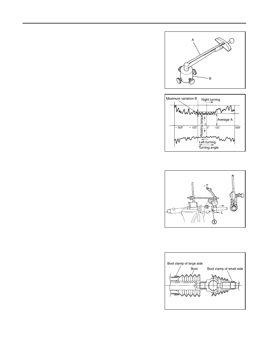
Adjust pinion rotating torque with the following procedure.

a.

Measure pinion rotating torque within 

±

180

°

 of neutral position

of the rack assembly using Tools. Stop the gear at the point
where highest torque is read.

b.

Loosen adjusting screw and retighten to 5.4 N·m (0.55 kg-m, 48
in-lb), and then loosen by 20 to 40

°

.

c.

Measure pinion rotating torque using Tools to make sure that the
measured value is within the standard. Readjust if the value is
outside the standard. Replace steering gear assembly if the
value is outside the standard after readjusting or adjusting screw
rotating torque is 5 N·m (0.51 kg-m, 44 in-lb) or less.

d.

Apply recommended liquid gasket to inner socket and turn pinion fully to left with inner socket installed to
gear housing assembly.

e.

Install dial gauge at 5 mm (0.20 in) (L) from the edge of gear
housing assembly (1), and tooth point.

f.

Measure vertical movement of rack assembly when pinion is
turned clockwise with torque of 19.6 N·m (2.0 kg-m, 14 ft-lb).
Readjust adjusting screw angle if the measured value is outside
the standard.

• If reading is outside of the specification, readjust screw angle

with adjusting screw.

CAUTION:

• If reading is still out side of specification, or if the rotating torque of adjusting screw is less

than 5 N·m (0.51 kg-m, 44 in-lb), replace steering gear assembly.

• Never turn adjusting screw more than twice.
• Replace steering gear assembly when adjusting screw is removed or more than twice.

9.

Install large end of boot to gear housing assembly.

10. Install small end of boot to inner socket boot mounting groove.
11. Install boot clamp to boot small end.

12. Install boot clamp to the large side of boot with the following procedure.

CAUTION:

Never reuse boot clamp.

A: Preload gauge [SST: ST3127S000 (J-25765-A)]

B: Preload adapter [SST: KV48103400 (

)]

SGIA1383E

Pinion rotating torque

Around neutral position 
(within

±

100

°

) average “A”

: 1.95 – 2.58 N·m (0.20 – 
0.26 kg-m, 18 – 22 in-lb)

Maximum variation “B”

: 0.98 N·m (0.10 kg-m, 9.0 
in-lb)

Vertical movement

: 0.265 mm (0.0104 in)

SGIA0936E

JSGIA0104ZZ

SGIA1325E

STEERING GEAR AND LINKAGE

ST-31

< ON-VEHICLE REPAIR >

C

D

E

F

H

I

J

K

L

M

A

B

ST

N

O

P

a.

Tighten large side of boot with boot clamp (stainless wire).

b.

Wrap clamp around boot groove for two turns. Insert a flat-
bladed screwdriver in loops on both ends of wire. Twist 4 to 4.5
turns while pulling them with force of approximately 98 N (10 kg,
22 lb).

c.

Twist boot clamp as shown. Pay attention to relationship
between winding and twisting directions.

d.

Twisted area (A) of clamp is in the opposite side of adjusting
screw (1) as shown in the figure (to prevent contact with other
parts). 

e.

Bent cut end of the wire as shown in the figure after twisting the
wire 4 to 4.5 turns so that cut end does not contact with boot.

CAUTION:

Keep gap from cylinder tube 5 mm (0.20 in) or more.

13. Install cylinder tubes to gear housing assembly.

14. Install low pressure piping.

Wire length “L”

: 370 mm (14.57 in)

SGIA0163E

SGIA0164E

JSGIA0101ZZ

Wire angle “A”

: 45

°

JSGIA0102ZZ

ST-32

< ON-VEHICLE REPAIR >

STEERING GEAR AND LINKAGE

15. Adjust inner socket to standard length “L”, and then tighten lock

nut to the specified torque. Check length “L” again after tighten-
ing lock nut.

CAUTION:

Adjust toe-in after this procedure. Length achieved after
toe-in adjustment is not necessary the above value.

2WD : Inspection

INFOID:0000000000958677

INSPECTION AFTER INSTALLATION

• Check if steering wheel turns smoothly when it is turned several times fully to the end of the left and right.
• Check the steering wheel play, neutral position steering wheel, steering wheel turning force, and front wheel

turning angle. Refer to 

ST-12, "Inspection"

.

• Check the fluid level, fluid leakage, and air bleeding hydraulic system. Refer to 

ST-10, "Inspection"

.

• Perform 4WAS front actuator neutral position adjustment. Refer to 

STC-27, "4WAS FRONT ACTUATOR

NEUTRAL POSITION ADJUSTMENT : Description"

.

INSPECTION AFTER DISASSEMBLY

Boot

• Check boot for cracks, and replace it if a malfunction is detected.

Rack Assembly

• Check rack for damage or wear, and replace it if a malfunction is detected.

Gear-Sub Assembly

• Check gear-sub assembly for damage or wear, and replace it if a malfunction is detected.
• Rotate gear-sub assembly and check for torque variation or rattle, and replace it if a malfunction is detected.

Gear Housing Assembly

• Check gear housing assembly for damage and scratches (inner wall). Replace if there are.

Outer Socket and Inner Socket

• Check the following items and replace the component if it does not meet the standard.

BALL JOINT SWINGING TORQUE

• Hook a spring balance at the point shown in the figure and pull the

spring balance. Make sure that the spring balance reads the spec-
ified value when ball stud and inner socket start to move. Replace
outer socket and inner socket if they are outside the standard.

BALL JOINT ROTATING TORQUE

Standard

Inner socket length “L”

: Refer to 

ST-60, "Inner 

Socket Length"

.

SGIA0167E

Standard for outer socket

(Measuring point: Stud cotter pin mounting hole)

Spring balance measure-
ment

: Refer to 

ST-59, "Socket 

Swing Force and Rotating 
Torque"

.

Standard for inner socket

(Measuring point: “*” mark shown in the figure)

Spring balance measure-
ment

: Refer to 

ST-59, "Socket 

Swing Force and Rotating 
Torque"

.

SGIA0896E

STEERING GEAR AND LINKAGE

ST-33

< ON-VEHICLE REPAIR >

C

D

E

F

H

I

J

K

L

M

A

B

ST

N

O

P

• Make sure that the reading is within the following specified range

using preload gauge (A) [SST: ST3127S000 (J-25765-A)]. Replace
outer socket if the reading is outside the specified value.

BALL JOINT AXIAL END PLAY

• Apply an axial load of 490 N (50 kg, 110 lb) to ball stud. Using a

dial gauge, measure amount of stud movement, and then make
sure that the value is within the following specified range. Replace
outer socket (1) and inner socket (2) if the measured value is out-
side the standard.

AWD

AWD : Exploded View

INFOID:0000000000958678

REMOVAL AND INSTALLATION

DISASSEMBLY AND ASSEMBLY

Standard

Outer socket rotating 
torque

: Refer to 

ST-59, "Socket 

Swing Force and Rotating 
Torque"

.

SGIA1382E

Standard

Outer socket

Refer to 

ST-60, "Socket Axial 

End Play"

.

Inner socket

: Refer to 

ST-60, "Socket Axial 

End Play"

.

JSGIA0109ZZ

1.

Steering gear assembly

2.

cotter pin

: Vehicle front

Refer to 

GI-4, "Components"

 for symbols in the figure.

JSGIA0039GB


Content   ..  1268  1269  1270  1271   ..