Infiniti G35 (V35) Sedan. Manual - part 1271


  Index      Infiniti     Infiniti G35 (V35) Sedan - service repair manual 2007 year


Search            


Content   ..  1269  1270  1271  1272   ..


Infiniti G35 (V35) Sedan. Manual - part 1271


ST-34

< ON-VEHICLE REPAIR >

STEERING GEAR AND LINKAGE

AWD : Removal and Installation

INFOID:0000000000958679

REMOVAL

1.

Set vehicle to the straight-ahead position.

2.

Remove tires with a power tool.

3.

Remove front cross bar. Refer to 

FSU-40, "Removal and Installation"

.

4.

Remove cotter pin (1), and then loosen the nut.

5.

Remove steering outer socket (2) from steering knuckle (3) so
as not to damage ball joint boot (4) using suitable ball joint
remover.

CAUTION:

Temporarily tighten the nut to prevent damage to threads
and to prevent the ball joint remover from suddenly coming
off.

6.

Remove high pressure piping and low pressure piping of
hydraulic piping, and then drain power steering fluid.
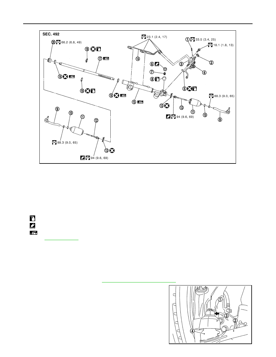
1.

Low pressure piping

2.

Rear cover cap

3.

Gear-sub assembly

4.

Power steering solenoid valve

5.

O-ring

6.

Adjusting screw

7.

Spring

8.

Retainer

9.

Outer socket

10. Boot clamp

11.

Boot

12. Inner socket

13. Boot clamp (stainless wire)

14. Cylinder tube

15. Gear housing assembly

16. Rack oil seal

17. Rack assembly

18. Rack Teflon ring

19. O-ring

20. End cover assembly

: Apply power steering fluid.

: Apply Genuine Liquid Gasket, Three Bond 1111B or equivalent.

: Apply multi-purpose grease.

Refer to 

GI-4, "Components"

 for symbols not described on the above.

JSGIA0120GB

SGIA1183E

STEERING GEAR AND LINKAGE

ST-35

< ON-VEHICLE REPAIR >

C

D

E

F

H

I

J

K

L

M

A

B

ST

N

O

P

7.

Remove steering hydraulic piping bracket from steering gear
assembly.

8.

Remove power steering solenoid valve harness connector (1).

9.

Remove lower joint fixing bolt (steering gear side).

10. Separate the lower shaft from the steering gear assembly by

sliding the slide shaft (A: sliding range).

CAUTION:

Spiral cable may be cut if steering wheel turns while sepa-
rating steering column assembly and steering gear assem-
bly. Be sure to secure steering wheel using string to avoid
turning.

11. Set a suitable jack to transmission assembly.

12. Remove the mounting nuts and bolts on the lower side of shock

absorber arm with a power tool, and then remove shock
absorber arm from transverse link. Refer to 

FSU-40, "Removal

and Installation"

.

13. Set a suitable jack to front suspension member.

14. Remove the mounting bolts and nuts of steering gear assembly.

15. Remove the mounting nuts of engine mounting insulator. Refer to 

EM-81, "AWD : Exploded View"

.

16. Remove the mounting nuts of front suspension member with a power tool. Refer to 

FSU-39, "Exploded

View"

.

17. Set an appropriate jack and lower it to the position where the steering gear assembly can be removed.

CAUTION:

• Move the jack slowly when lowering it.
• Support the steering gear assembly so that it will not drop.

18. Remove steering gear assembly.

INSTALLATION

Note the following, and install in the reverse order of removal.

CAUTION:

Spiral cable may be cut if steering wheel turns while separating steering column assembly and steer-
ing gear assembly. Be sure to secure steering wheel using string to avoid turning.

: Vehicle front

JSGIA0043ZZ

JSGIA0040ZZ

JSGIA0035ZZ

ST-36

< ON-VEHICLE REPAIR >

STEERING GEAR AND LINKAGE

• When installing suction hose (1), refer to the figure.

CAUTION:

• Never apply fluid to the hose (1) and tube (2).
• Insert hose securely until it contacts spool (A) of tube.
• Install clamp (3) to the hose at 3 – 8 mm (0.12 – 0.31 in) (L)

from the edge of the hose.

• When installing lower joint to steering gear assembly, follow the procedure listed below.
- Set rack of steering gear in the neutral position.

NOTE:
To get the neutral position of rack, turn gear-sub assembly and measure the distance of inner socket, and
then measure the intermediate position of the distance.

- Align rear cover cap projection (A) with the marking position of

gear housing assembly (B).

- Install slit part of lower joint (C) aligning with the rear cover cap

projection (A). Make sure that the slit part of lower joint (C) is
aligned with rear cover cap projection (A) and the marking position
of gear housing assembly (B).

• After installation, bleed air from the steering hydraulic system.

Refer to 

ST-10, "Inspection"

.

• Perform final tightening of nuts and bolts on each part under

unladen conditions with tires on level ground when removing steer-
ing gear assembly. Check wheel alignment. Refer to 

FSU-28,

"Wheel Alignment Inspection"

.

• Adjust neutral position of steering angle sensor after checking wheel alignment. Refer to 

BRC-8, "ADJUST-

MENT OF STEERING ANGLE SENSOR NEUTRAL POSITION : Special Repair Requirement"

.

AWD : Disassembly and Assembly

INFOID:0000000000958680

DISASSEMBLY

1.

Remove low pressure piping.

CAUTION:

• Disassemble and assemble steering gear assembly by fixing the mounting area with a vise using

copper plates.

• Clean steering gear assembly with kerosene before disassembling. Be careful to avoid splash-

ing or applying any kerosene over connector of discharge port or return port.

2.

Remove cylinder tubes from gear housing assembly.

3.

Remove rear cover cap from gear-sub assembly.

4.

Measure adjusting screw height “H”, and loosen adjusting
screw.

CAUTION:

• Never loosen adjusting screw 2 turns or more.
• Replace steering gear assembly if adjusting screw is

loosened 2 turns or more and it is removed.

5.

Remove gear-sub assembly from gear housing assembly.

6.

Remove O-ring from gear housing assembly.

7.

Loosen outer socket lock nut, and remove outer socket.

8.

Remove boot clamps, and then remove boot from inner socket.

CAUTION:

Never damage inner socket and gear housing assembly when removing boot. Inner socket and
gear housing assembly must be replaced if inner socket and gear housing assembly are damaged
because it may cause foreign material interfusion.

9.

Remove inner socket from gear housing assembly.

JSGIA0118ZZ

JSGIA0111ZZ

SGIA0624E

STEERING GEAR AND LINKAGE

ST-37

< ON-VEHICLE REPAIR >

C

D

E

F

H

I

J

K

L

M

A

B

ST

N

O

P

10. Drill out the clinching part of gear housing assembly (end cover

assembly side) outer rim with a 3 mm (0.12 in) drill bit. [Drill for
approximately 1.5 mm (0.059 in) depth.]

11. Remove end cover assembly with a 36 mm (1.42 in) open head

(suitable tool).

CAUTION:

Never damage rack assembly surface when removing. Rack
assembly must be replaced if damaged because it may
cause fluid leakage.

12. Pull rack assembly together with rack oil seal (outer side) out

from gear housing assembly.

CAUTION:

Never damage cylinder inner wall when remove rack
assembly. Gear housing assembly must be replaced if dam-
aged because it may cause fluid leakage.

13. Heat rack Teflon ring to approximately 40

°

C (104

°

F) with a

dryer, and remove rack Teflon ring and O-ring from rack assem-
bly.

CAUTION:

Never damage rack assembly. Rack assembly must be
replaced if damaged because it may cause fluid leakage.

14. Push rack oil seal inside with a 29 mm (1.14 in) socket and an

extension bar to push out rack oil seal (inner side) from gear
housing assembly.

CAUTION:

Never damage gear housing assembly and cylinder inner
wall. Gear housing assembly must be replaced if damaged
because it may cause fluid leakage.

ASSEMBLY

1.

Apply recommended fluid to O-ring. Put an O-ring into a rack Teflon ring.

STC0013D

SST081B

SGIA0151E

SGIA0179E


Content   ..  1269  1270  1271  1272   ..