Infiniti G35 (V35) Sedan. Manual - part 1268


  Index      Infiniti     Infiniti G35 (V35) Sedan - service repair manual 2007 year


Search            


Content   ..  1266  1267  1268  1269   ..


Infiniti G35 (V35) Sedan. Manual - part 1268


ST-22

< ON-VEHICLE REPAIR >

LOWER SHAFT

DISASSEMBLY AND ASSEMBLY

WITH 4WAS : Removal and Installation

INFOID:0000000000958671

REMOVAL

1.

Set vehicle to the straight-ahead position.

2.

Perform 4WAS front actuator neutral position adjustment. Refer to 

STC-27, "4WAS FRONT ACTUATOR

NEUTRAL POSITION ADJUSTMENT : Description"

. (4WAS models)

3.

Fix the steering wheel.
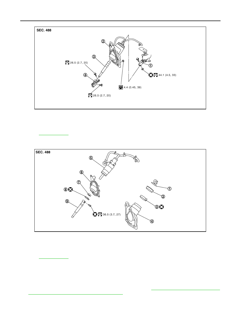
1.

Steering column assembly

2.

Hole cover assembly

3.

Lower shaft (With 4WAS front actua-
tor)

4.

Lower joint

Refer to 

GI-4, "Components"

 for symbols in the figure.

JSGIA0036GB

1.

Collar

2.

Hole cover seal

3.

Clamp

4.

Hole cover

5.

4WAS front actuator

6.

Hole cover (lower)

7.

Hole cover seal (lower)

8.

Clamp (lower)

9.

Slide shaft

Refer to 

GI-4, "Components"

 for symbols in the figure.

JSGIA0087GB

LOWER SHAFT

ST-23

< ON-VEHICLE REPAIR >

C

D

E

F

H

I

J

K

L

M

A

B

ST

N

O

P

4.

Fix the lower shaft (with 4WAS front actuator) so that the posi-
tions (A) and (B) are aligned.

CAUTION:

Never damage the lower shaft (with 4WAS front actuator)
and hole cover.

5.

Remove lower joint fixing bolt (steering gear side).

6.

Separate the lower shaft (with 4WAS front actuator) from the
steering gear assembly by sliding the slide shaft (A: sliding
range).

CAUTION:

Spiral cable may be cut if steering wheel turns while sepa-
rating steering column assembly and steering gear assem-
bly. Be sure to secure steering wheel using string to avoid
turning.

7.

Remove the 4WAS front control unit. Refer to 

STC-177,

"Removal and Installation"

.

8.

Remove the accelerator pedal bracket and lever assembly.

9.

Remove the foot grille (right). Refer to 

VTL-50, "FOOT GRILLES

: Removal and Installation"

.

10. Remove the hole cover mounting nuts.

11. Remove the upper joint fixing bolt and nuts (lower shaft side).

12. Remove the lower shaft (with 4WAS front actuator) and hole cover assembly.

CAUTION:

Never damage the lower shaft (with 4WAS front actuator) and hole cover.

INSTALLATION

Note the following, and install in the reverse order of removal.

CAUTION:

Spiral cable may be cut if steering wheel turns while separating steering column assembly and steer-
ing gear assembly. Be sure to secure steering wheel using string to avoid turning.
• When installing lower joint to steering gear assembly, follow the procedure listed below.
- Set rack of steering gear in the neutral position.

NOTE:
To get the neutral position of rack, turn gear-sub assembly and measure the distance of inner socket, and
then measure the intermediate position of the distance.

- Align rear cover cap projection (A) with the marking position of

gear housing assembly (B).

- Install slit part of lower joint (C) aligning with the rear cover cap

projection (A). Make sure that the slit part of lower joint (C) is
aligned with rear cover cap projection (A) and the marking position
of gear housing assembly (B).

• Adjust neutral position of steering angle sensor. Refer to 

BRC-8,

"ADJUSTMENT OF STEERING ANGLE SENSOR NEUTRAL
POSITION : Special Repair Requirement"

.

• Check the following after installation:
- Check if steering wheel turns smoothly when it is turned several

times fully to the end of the left and right.

- Check the steering wheel play, neutral position steering wheel, steering wheel turning force, and front wheel

turning angle. Refer to 

ST-12, "Inspection"

.

- Perform 4WAS front actuator neutral position adjustment. Refer to 

STC-27, "4WAS FRONT ACTUATOR

NEUTRAL POSITION ADJUSTMENT : Description"

.

WITH 4WAS : Inspection

INFOID:0000000000958672

JSGIA0037ZZ

JSGIA0088ZZ

JSGIA0111ZZ

ST-24

< ON-VEHICLE REPAIR >

LOWER SHAFT

• Check the sliding range of the lower shaft (with 4WAS front actua-

tor).

CAUTION:

Check the sliding range (A) (between the extended position
and the contracted position) of the lower shaft (with 4WAS
front actuator).

• Check each part of lower shaft (4WAS front actuator) for damage

or other malfunctions. Replace if there are.

WITH 4WAS : Disassembly and Assembly

INFOID:0000000000958673

DISASSEMBLY

CAUTION:

Never rotate the 4WAS front actuator and the spiral cable counterclockwise (actuator upper side).
1.

Remove the collar.

2.

Remove the slide shaft.

3.

Remove the clamp (lower) and the hole cover seal (lower) from the hole cover (lower).

4.

Remove the hole cover (lower) from the hole cover.

5.

Remove the clamp, the hole cover seal and the 4WAS front actuator from the hole cover.

ASSEMBLY

1.

Perform the spiral cable neutral adjustment as per the following procedure.

a.

Rotate the spiral cable (1) clockwise (

) slowly until it stops.

b.

Rotate the spiral cable 2.5 turning counterclockwise (

) slowly.

Align the spiral cable with the notch (A).
NOTE:
The spiral cable turns approximately 5 turning in maximum.

2.

Install the 4WAS front actuator and the hole cover seal to the
hole cover, and install the clamp to the hole cover.

CAUTION:

• Assemble the clamp so as not to misalign the spiral cable

position.

• Never reuse the clamp.

3.

Install the collar (1) to the 4WAS front actuator. Do not misalign
the positions (A) and (B).

CAUTION:

Never damage the collar (1) and the hole cover (2).

4.

Assemble the actuator harness to the hole cover.

Standard

Sliding range

: Refer to 

ST-59, "Lower Shaft 

Sliding Range"

.

JSGIA0088ZZ

JSGIA0089ZZ

JSGIA0090ZZ

LOWER SHAFT

ST-25

< ON-VEHICLE REPAIR >

C

D

E

F

H

I

J

K

L

M

A

B

ST

N

O

P

5.

Install the hole cover (lower) to the hole cover.

CAUTION:

Assemble the 4 hole cover (lower) pawls (

) to the hole

cover securely.

6.

Install the hole cover seal (lower) to the hole cover (lower), and
install the clamp (lower).

CAUTION:

Never reuse the clamp (lower).

7.

Install the slide shaft to the actuator.

CAUTION:

Never reuse the bolt.

JSGIA0091ZZ


Content   ..  1266  1267  1268  1269   ..