Content .. 1075 1076 1077 1078 ..
Infiniti FX35, FX50 (S51). Manual - part 1077
FAX-6
< REMOVAL AND INSTALLATION >
[2WD]
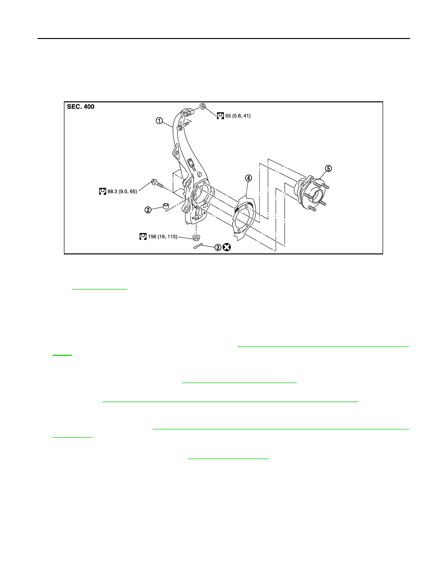
FRONT WHEEL HUB AND KNUCKLE
REMOVAL AND INSTALLATION
FRONT WHEEL HUB AND KNUCKLE
Exploded View
INFOID:0000000005248975
Removal and Installation
INFOID:0000000005248976
REMOVAL
1.
Remove tires with power tool.
2.
Remove wheel sensor and sensor harness. Refer to
BRC-131, "FRONT WHEEL SENSOR : Exploded
.
CAUTION:
Never pull on wheel sensor harness.
3.
Remove brake hose bracket. Refer to
BR-20, "FRONT : Exploded View"
.
4.
Remove caliper assembly with power tool. Hang caliper assembly in a place where it will not interfere with
work. Refer to
BR-43, "BRAKE CALIPER ASSEMBLY (2 PISTON TYPE) : Exploded View"
.
CAUTION:
Never depress brake pedal while brake caliper is removed.
5.
Remove disc rotor. Refer to
BR-44, "BRAKE CALIPER ASSEMBLY (2 PISTON TYPE) : Removal and
.
6.
Remove wheel hub and bearing assembly, and then remove splash guard.
7.
Remove steering outer socket. Refer to
8.
Remove cotter pin of transverse link and steering knuckle, and then loosen nut.
9.
Separate steering knuckle from upper link.
10. Separate steering knuckle from transverse link so as not to damage ball joint boot using the ball joint
remover, and remove steering knuckle.
CAUTION:
Temporarily tighten the nut to prevent damage to threads and to prevent the ball joint remover
from suddenly coming off.
INSTALLATION
Note the following, and install in the reverse order of the removal.
1.
Steering knuckle
2.
Ball seat
3.
Cotter pin
4.
Splash guard
5.
Wheel hub and bearing assembly
Refer to
for symbols in the figure.
JPDIF0189GB