Infiniti EX35. Manual - part 551


  Index      Infiniti     Infiniti EX35 - service repair manual 2008 year


Search            


Content   ..  549  550  551  552   ..


Infiniti EX35. Manual - part 551


DLN-154

< ON-VEHICLE REPAIR >

[REAR FINAL DRIVE: R200]

FRONT OIL SEAL

d.

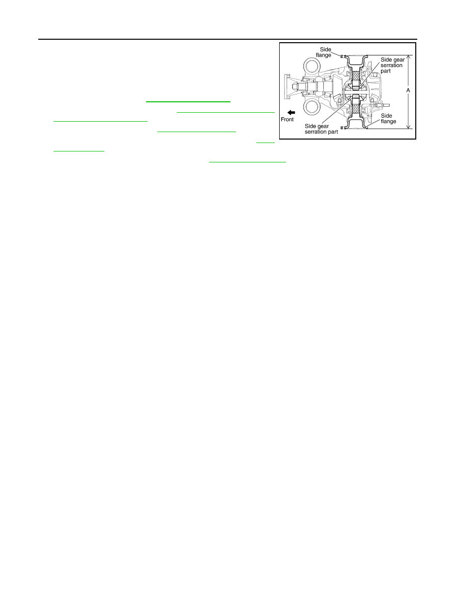
Confirm that the dimension of the side flange installation mea-
surement (A) in the figure comes into the following.

11. Install drive shaft. Refer to 

RAX-9, "Exploded View"

.

12. Install rear wheel sensor. Refer to 

BRC-107, "FRONT WHEEL

SENSOR : Exploded View"

.

13. Install center muffler. Refer to 

EX-5, "Exploded View"

.

14. Refill gear oil to the final drive and check oil level. Refer to 

DLN-

143, "Refilling"

.

15. Check the final drive for oil leakage. Refer to 

DLN-143, "Inspection"

.

Standard

A

: 326 – 328 mm (12.83 – 12.91 in)

SDIA1039E

SIDE OIL SEAL

DLN-155

< ON-VEHICLE REPAIR >

[REAR FINAL DRIVE: R200]

C

E

F

G

H

I

J

K

L

M

A

B

DLN

N

O

P

SIDE OIL SEAL

2WD

2WD : Exploded View

INFOID:0000000003135823

1.

Drive pinion lock nut

2.

Companion flange

3.

Front oil seal

4.

Pinion front bearing

5.

Gear carrier

6.

Side oil seal

7.

Side flange

8.

Collapsible spacer

9.

Pinion rear bearing

10. Pinion height adjusting washer

11.

Drive pinion

12. Side bearing adjusting washer

13. Side bearing

14. Side gear thrust washer

15. Circular clip

16. Side gear

17. Lock pin

18. Pinion mate gear

19. Pinion mate thrust washer

20. Pinion mate shaft

21. Drive gear

22. Differential case

23. Bearing cap

24. Filler plug

25. Gasket

26. Rear cover

27. Drain plug

A.

Oil seal lip

B.

Screw hole

C.

For the tightening torque, refer to 

DLN-166, "2WD : Assembly"

.

: Apply gear oil.

: Apply anti-corrosion oil.

: Apply Genuine Silicone RTV or equivalent. Refer to 

GI-15, "Recommended Chemical Products and Sealants"

.

: Apply Genuine High Strength Thread Locking Sealant or equivalent. Refer to 

GI-15, "Recommended Chemical Products 

and Sealants"

.

Refer to 

GI-4, "Components"

 for symbols not described above.

JPDID0129GB

DLN-156

< ON-VEHICLE REPAIR >

[REAR FINAL DRIVE: R200]

SIDE OIL SEAL

2WD : Removal and Installation

INFOID:0000000003135824

REMOVAL

1.

Remove center muffler with a power tool. Refer to 

EX-5, "Exploded View"

.

2.

Remove rear wheel sensor. Refer to 

BRC-107, "FRONT WHEEL SENSOR : Exploded View"

.

3.

Remove drive shaft from final drive with a power tool. Then suspend it by wire, etc. Refer to 

RAX-9,

"Exploded View"

.

4.

Install attachment (A) [SST: KV40104100 (

)] to side

flange, and then pull out the side flange with the sliding hammer
(B) [SST: ST36230000 (J-25840-A)].
NOTE:
Circular clip installation position: Final drive side

5.

Remove side oil seal, using a flat-bladed screwdriver.

CAUTION:

Never damage gear carrier.

INSTALLATION

1.

Apply multi-purpose grease to side oil seal lips.

2.

Install side oil seal until it becomes flush with the case end,
using the drift [SST: KV38100200 (J-26233)].

CAUTION:

• Never reuse oil seal.
• When installing, never incline oil seal.

3.

Install side flange with the following procedure.

a.

Attach the protector [SST: KV38107900 (J-39352)] to side oil
seal.

b.

After the side flange is inserted and the serrated part of side
gear has engaged the serrated part of flange, remove the pro-
tector.

c.

Put a suitable drift on the center of side flange, then drive it until sound changes.

JSDIA0105ZZ

SDIA1584E

SDIA1585E

SDIA0822E

SIDE OIL SEAL

DLN-157

< ON-VEHICLE REPAIR >

[REAR FINAL DRIVE: R200]

C

E

F

G

H

I

J

K

L

M

A

B

DLN

N

O

P

NOTE:
When installation is completed, driving sound of the side flange turns into a sound that seems to affect the
whole final drive.

d.

Confirm that the dimension of the side flange (1) installation
measurement (A) in the figure comes into the following.

4.

Install drive shaft. Refer to 

RAX-9, "Exploded View"

.

5.

Install rear wheel sensor. Refer to 

BRC-107, "FRONT WHEEL

SENSOR : Exploded View"

.

6.

Install center muffler. Refer to 

EX-5, "Exploded View"

.

7.

When oil leaks while removing, check oil level after the installa-
tion. Refer to 

DLN-143, "Inspection"

.

AWD

AWD : Exploded View

INFOID:0000000003135825

Standard

A

: 326 – 328 mm (12.83 – 12.91 in)

JSDIA0106ZZ

1.

Drive pinion lock nut

2.

Companion flange

3.

Front oil seal

4.

Pinion front bearing

5.

Gear carrier

6.

Side oil seal

7.

Side flange

8.

Collapsible spacer

9.

Pinion rear bearing

10. Pinion height adjusting washer

11.

Drive pinion

12. Side bearing adjusting washer

13. Side bearing

14. Side gear thrust washer

15. Circular clip

16. Side gear

17. Lock pin

18. Pinion mate gear

19. Pinion mate thrust washer

20. Pinion mate shaft

21. Drive gear

22. Differential case

23. Bearing cap

24. Filler plug

JSDIA0027GB


Content   ..  549  550  551  552   ..