Infiniti EX35. Manual - part 550
DLN-150
< ON-VEHICLE REPAIR >
[REAR FINAL DRIVE: R200]
FRONT OIL SEAL
AWD : Removal and Installation
INFOID:0000000003135822
REMOVAL
CAUTION:
Verify identification stamp of replacement frequency put in the lower part of gear carrier to determine
replacement for collapsible spacer when replacing front oil seal. Refer to “Identification stamp of
replacement frequency of front oil seal”. If collapsible spacer replacement is necessary, remove final
drive assembly and disassemble it to replace front oil seal and collapsible spacer. Refer to
"AWD : Removal and Installation"
and
NOTE:
The reuse of collapsible spacer is prohibited in principle. However, it is reusable on a one-time basis
only in cases when replacing front oil seal.
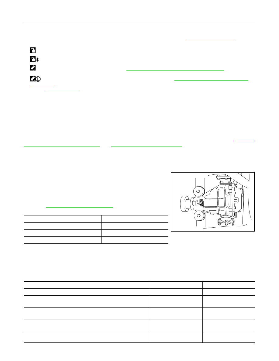
Identification stamp of replacement frequency of front oil seal
• The diagonally shaded area in the figure shows stamping point for
replacement frequency of front oil seal.
• The following table shows if collapsible spacer replacement is
needed before replacing front oil seal.
When collapsible spacer replacement is required, disassemble
final drive assembly to replace collapsible spacer and front oil seal.
Refer to
.
CAUTION:
Make a stamping after replacing front oil seal.
• After replacing front oil seal, make a stamping on the stamping point in accordance with the table below in
order to identify replacement frequency.
CAUTION:
Make a stamping from left to right.
25. Gasket
26. Rear cover
27. Drain plug
A.
Oil seal lip
B.
Screw hole
C.
For the tightening torque, refer to
.
: Apply gear oil.
: Apply anti-corrosion oil.
: Apply Genuine Silicone RTV or equivalent. Refer to
GI-15, "Recommended Chemical Products and Sealants"
.
: Apply Genuine High Strength Thread Locking Sealant or equivalent. Refer to
GI-15, "Recommended Chemical Products
Refer to
for symbols not described above.
Stamp
collapsible spacer replacement
No stamp
Not required
“0” or “0” on the far right of stamp
Required
“01” or “1” on the far right of stamp
Not required
PDIA0976E
Stamp before stamping
Stamping on the far right
Stamping
No stamp
0
0
“0”
(Front oil seal was replaced once.)
1
01
“01”
(Collapsible spacer and front oil seal were replaced last time.)
0
010
“0” is on the far right.
(Only front oil seal was replaced last time.)
1
...01
“1” is on the far right.
(Collapsible spacer and front oil seal were replaced last time.)
0
...010