Infiniti EX35. Manual - part 1469


  Index      Infiniti     Infiniti EX35 - service repair manual 2008 year


Search            


Content   ..  1467  1468  1469  1470   ..


Infiniti EX35. Manual - part 1469


TM-264

< DISASSEMBLY AND ASSEMBLY >

[5AT: RE5R05A]

MID SUN GEAR, REAR SUN GEAR, HIGH AND LOW REVERSE CLUTCH HUB

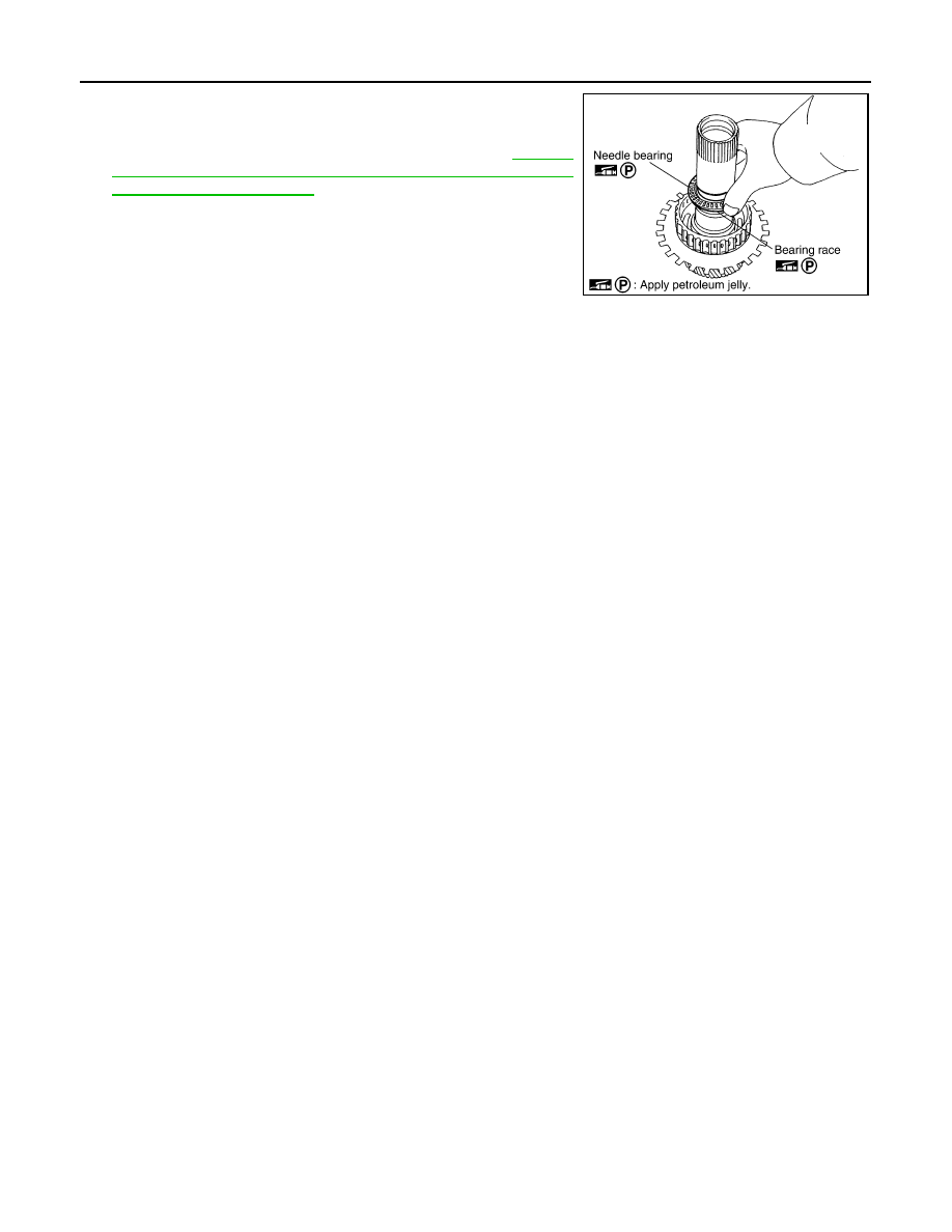
9.

Install needle bearing and bearing race to high and low reverse
clutch hub.

CAUTION:

Check the direction of needle bearing. Refer to 

TM-207,

"Location of Adjusting Shims, Needle Bearings, Thrust
Washers and Snap Rings"

.

Inspection

INFOID:0000000003130665

• High and Low Reverse Clutch Hub Snap Ring, Rear Sun Gear Snap Ring

Check for deformation, fatigue or damage.

CAUTION:

If necessary, replace the snap ring.

• 1st One-way Clutch

Check frictional surface for wear or damage.

CAUTION:

If necessary, replace the 1st one-way clutch.

• Mid Sun Gear

Check for deformation, fatigue or damage.

CAUTION:

If necessary, replace the mid sun gear.

• Rear Sun Gear

Check for deformation, fatigue or damage.

CAUTION:

If necessary, replace the rear sun gear.

• High and Low Reverse Clutch Hub

Check for deformation, fatigue or damage.

CAUTION:

If necessary, replace the high and low reverse clutch hub.

SCIA2854E

HIGH AND LOW REVERSE CLUTCH

TM-265

< DISASSEMBLY AND ASSEMBLY >

[5AT: RE5R05A]

C

E

F

G

H

I

J

K

L

M

A

B

TM

N

O

P

HIGH AND LOW REVERSE CLUTCH

Exploded View

INFOID:0000000003130666

Disassembly

INFOID:0000000003130667

1.

Remove bearing race from high and low reverse clutch drum.

2.

Using a flat-bladed screwdriver, remove snap ring from high and
low reverse clutch drum.

3.

Remove drive plates, driven plates and retaining plate from high
and low reverse clutch drum.

Assembly

INFOID:0000000003130668

1.

Install drive plates, driven plates and retaining plate in high and low reverse clutch drum.

CAUTION:

1.

High and low reverse clutch drum

2.

Driven plate

3.

Retaining plate

4.

Snap ring

5.

Drive plate

6.

Bearing race

SCIA5239E

SCIA5215E

SCIA2868E

TM-266

< DISASSEMBLY AND ASSEMBLY >

[5AT: RE5R05A]

HIGH AND LOW REVERSE CLUTCH

Check the order of plates.

2.

Using a flat-bladed screwdriver, install snap ring in high and low
reverse clutch drum.

3.

Install bearing race to high and low reverse clutch drum.

CAUTION:

Check the direction of needle bearing. Refer to 

TM-207,

"Location of Adjusting Shims, Needle Bearings, Thrust
Washers and Snap Rings"

.

Inspection

INFOID:0000000003130669

Check the following, and replace transmission assembly if necessary.
• High and Low Reverse Clutch Snap Ring

Check for deformation, fatigue or damage.

• High and Low Reverse Clutch Drive Plates

Check facing for burns, cracks or damage.

• High and Low Reverse Clutch Retaining Plate and Driven Plates

Check facing for burns, cracks or damage.

1

:  Snap  ring

2

: Retaining plate

3

: Drive plate

4

: Driven plate

4/4

: Drive plate / Driven plate

SCIA6735E

SCIA2868E

SCIA5215E

DIRECT CLUTCH

TM-267

< DISASSEMBLY AND ASSEMBLY >

[5AT: RE5R05A]

C

E

F

G

H

I

J

K

L

M

A

B

TM

N

O

P

DIRECT CLUTCH

Exploded View

INFOID:0000000003130670

Disassembly

INFOID:0000000003130671

1.

Using a flat-bladed screwdriver, remove snap ring from direct
clutch drum.

2.

Remove drive plates, driven plates, dish plate and retaining
plates from direct clutch drum.

Assembly

INFOID:0000000003130672

1.

Install drive plates, driven plates, dish plate and retaining plates in direct clutch drum.

CAUTION:

Check the order of plates.

1.

Direct clutch drum

2.

Dish plate

3.

Retaining plate

4.

Driven plate

5.

Retaining plate

6.

Snap ring

7.

Drive plate

SCIA7015E

SCIA2868E

1

:  Snap  ring

2

: Retaining plate

3

: Drive plate

4

: Driven plate

5

: Dish plate

5 / 4

: Drive plate / Driven plate

SCIA6952E


Content   ..  1467  1468  1469  1470   ..