Content .. 1468 1469 1470 1471 ..
Infiniti EX35. Manual - part 1470
TM-268
< DISASSEMBLY AND ASSEMBLY >
[5AT: RE5R05A]
DIRECT CLUTCH
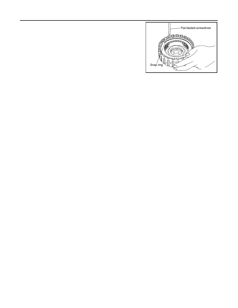
2.
Using a flat-bladed screwdriver, install snap ring in direct clutch
drum.
Inspection
INFOID:0000000003130673
Check the following, and replace direct clutch assembly if necessary.
• Direct Clutch Snap Ring
Check for deformation, fatigue or damage.
• Direct Clutch Drive Plates and Driven Plates
Check facing for burns, cracks or damage.
• Direct Clutch Dish Plate and Retaining Plates
Check facing for burns, cracks or damage.
SCIA2868E