Infiniti EX35. Manual - part 1448


  Index      Infiniti     Infiniti EX35 - service repair manual 2008 year


Search            


Content   ..  1446  1447  1448  1449   ..


Infiniti EX35. Manual - part 1448


TM-180

< ON-VEHICLE REPAIR >

[5AT: RE5R05A]

REVOLUTION SENSOR

REVOLUTION SENSOR

2WD

2WD : Exploded View

INFOID:0000000003130626

2WD : Removal and Installation

INFOID:0000000003130627

REMOVAL

1.

Disconnect the battery cable from the negative terminal.

2.

Drain ATF through drain plug.

3.

Remove exhaust front tube and center muffler with power tool. Refer to 

EX-5, "Exploded View"

.

4.

Remove rear propeller shaft. Refer to 

DLN-81, "Exploded View"

.

5.

Remove control rod. Refer to 

TM-161, "Exploded View"

.

6.

Remove exhaust mounting bracket. Refer to 
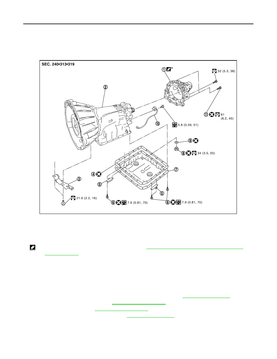
EX-5, "Exploded View"

.

1.

Rear extension

2.

A/T

3.

Bracket

4.

Oil pan gasket

5.

Clip

6.

Oil pan mounting bolt

7.

Oil pan

8.

Drain plug

9.

Drain plug gasket

10.

Revolution sensor

11.

Self-sealing bolt

*

: Apply Genuine Anaerobic Liquid Gasket or equivalent. Refer to 

GI-15, "Recommended Chemical Products and Sealants"

.

Refer to 

GI-4, "Components"

 for symbols not described on the above.

SCIA8271E

REVOLUTION SENSOR

TM-181

< ON-VEHICLE REPAIR >

[5AT: RE5R05A]

C

E

F

G

H

I

J

K

L

M

A

B

TM

N

O

P

7.

Disconnect heated oxygen sensor 2 harness connectors (A).

8.

Remove heated oxygen sensor 2 harness (B) from clips (1).

9.

Remove bracket (2) from transmission assembly.

10. Remove clips (1).

11. Remove oil pan (2) and oil pan gasket.

12. Support A/T assembly with a transmission jack.

CAUTION:

When setting transmission jack, place wooden blocks to
prevent from damaging control valve with TCM and trans-
mission case.

13. Remove rear engine mounting member with power tool. Refer to 

EM-79, "2WD : Exploded View"

.

14. Remove engine mounting insulator (rear). Refer to 

EM-79, "2WD : Exploded View"

.

15. Remove tightening bolts for rear extension assembly and trans-

mission case.

16. Tap rear extension assembly with a soft hammer (A).

: Vehicle front

: Bolt

SCIA8269E

3

: Drain plug

: Vehicle front

: Oil pan mounting bolt

1

: Self-sealing bolt

A

:  Bolt

SCIA8117E

JPDIA0026ZZ

JPDIA0027ZZ

TM-182

< ON-VEHICLE REPAIR >

[5AT: RE5R05A]

REVOLUTION SENSOR

17. Remove rear extension assembly (with needle bearing) from

transmission case.

18. Disconnect revolution sensor connector (A).

CAUTION:

Be careful not to damage connector

19. Disengage terminal clip (

).

20. Remove revolution sensor (1) from transmission case.

CAUTION:

• Do not subject it to impact by dropping or hitting it.
• Do not disassemble.
• Do not allow metal filings, etc. to get on the sensor's front

edge magnetic area.

• Do not place in an area affected by magnetism.

INSTALLATION

Note the following, and install in the reverse order removal.

CAUTION:

• Insert the tip of parking rod between the parking pole and the parking actuator support when assem-

bling the rear extension assembly. 

• Do not reuse drain plug gasket.
• Refer to the followings when revolution sensor.

CAUTION:

• Do not subject it to impact by dropping or hitting it.
• Do not disassemble.
• Do not allow metal filings, etc. to get on the sensor's front edge magnetic area.
• Do not place in an area affected by magnetism.

• Refer to the followings when installing rear extension assembly.

SCIA3431E

JPDIA0011ZZ

: Bolt

JPDIA0041ZZ

REVOLUTION SENSOR

TM-183

< ON-VEHICLE REPAIR >

[5AT: RE5R05A]

C

E

F

G

H

I

J

K

L

M

A

B

TM

N

O

P

- Apply recommended sealant (Genuine Anaerobic Liquid Gasket or

equivalent. Refer to 

GI-15, "Recommended Chemical Products

and Sealants"

.) to rear extension assembly as shown in the figure.

CAUTION:

Completely remove all moisture, oil and old sealant, etc. from
transmission case and rear extension assembly mounting
surfaces.

- Tighten rear extension assembly bolts to the specified torque.

• Refer to the followings when installing oil pan (2) (with oil pan gas-

ket) and clips (1) to transmission case.

CAUTION:

• Do not reuse oil pan gasket and oil pan mounting gasket.
• Install oil pan gasket in the direction to align hole position.
• Install it so that drain plug (3) comes to the position as

shown in the figure.

• Be careful not to pinch harnesses.
• Completely remove all moisture, oil and old gasket, etc. from oil pan mounting surface.

A

: Start and finish point shall be in the 
center of two bolts.

B

: 3 – 5 mm (0.12 – 0.20 in)

Sealant 
width (C)

: 1.0 – 2.0 mm (0.04 – 0.08 in)

Sealant 
height (C)

: 0.4 – 1.0 mm (0.016 – 0.04 in)

JPDIA0036ZZ

1

: Self-searing bolt

A

:  Bolt

JPDIA0026ZZ

: Vehicle front

: Oil pan mounting bolt

SCIA8117E


Content   ..  1446  1447  1448  1449   ..