Honda Ridgeline. Manual - part 515
*05
*06
*07
−
−
−
−
−
−
YES
NO
YES
NO
YES
NO
23-26
Audio System
Symptom Troubleshooting (cont’d)
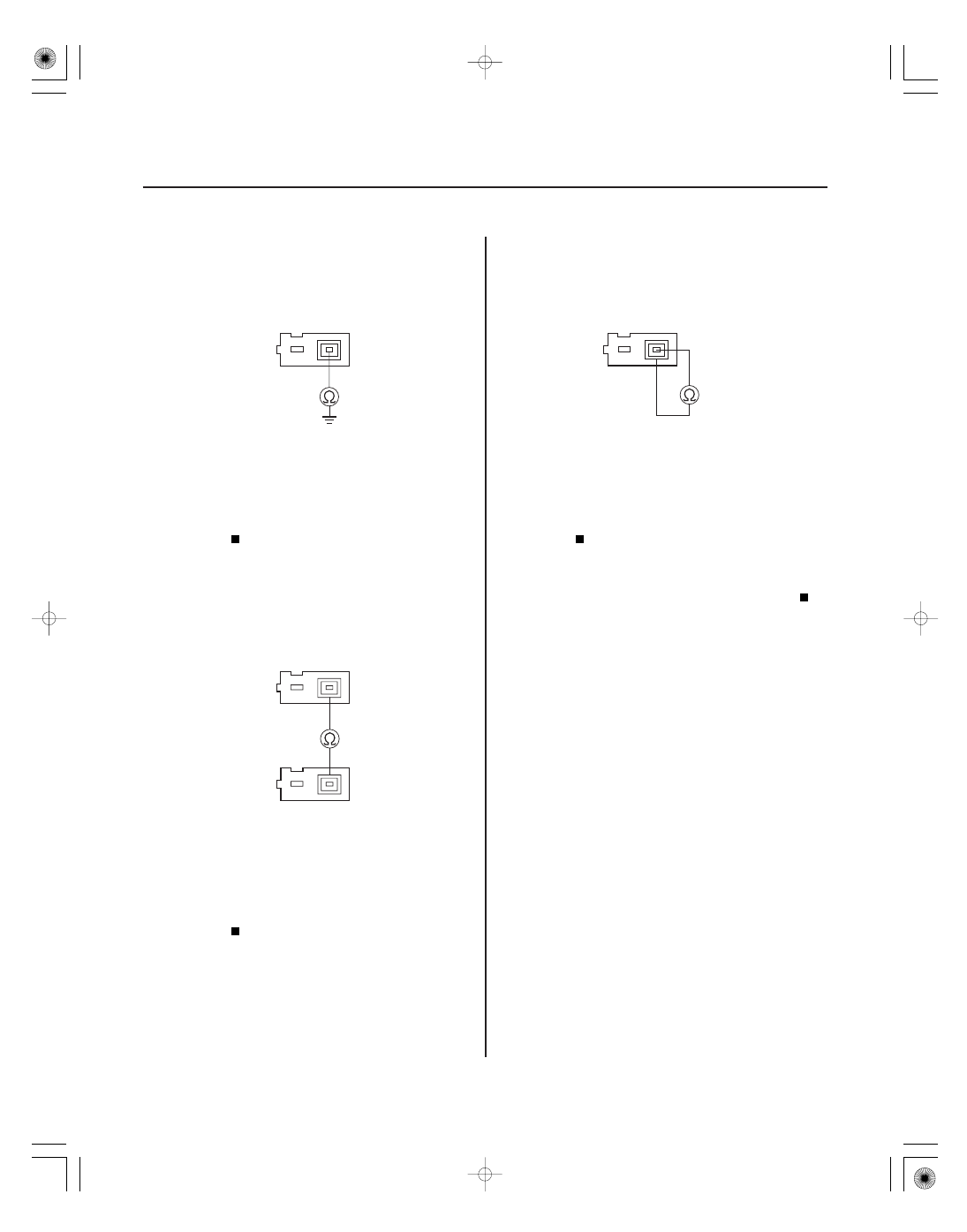
AUDIO UNIT CONNECTOR E (3P)
RF IN
AUDIO UNIT CONNECTOR E (3P)
AM/FM ANTENNA AMPLIFIER 3P CONNECTOR
RF SH
RF SH
AUDIO UNIT CONNECTOR E (3P)
RF IN
RF SH
20. Check for continuity between the audio unit
connector E (3P) No. 1 terminal and body ground.
Replace the AM/FM antenna lead and/or
sublead.
Go to step 21.
21. Check for continuity between the audio unit
connector E (3P) No. 2 terminal and the AM/FM
antenna amplifier 3P connector No. 2 terminal.
Go to step 22.
Replace the AM/FM antenna lead and/or
sublead.
22. Check for continuity between the audio unit
connector E (3P) No. 1 and No. 2 terminals.
Replace the AM/FM antenna lead and/or
sublead.
Replace the AM/FM antenna amplifier
(see page 23-62), and recheck. If the reception is
still poor, replace the audio unit (see page 23-57).
Terminal side of female terminals
Terminal side of female terminals
Terminal side of female terminals
Terminal side of female terminals
Is ther e continuity?
Is ther e continuity?
Is ther e continuity?