Honda Ridgeline. Manual - part 456
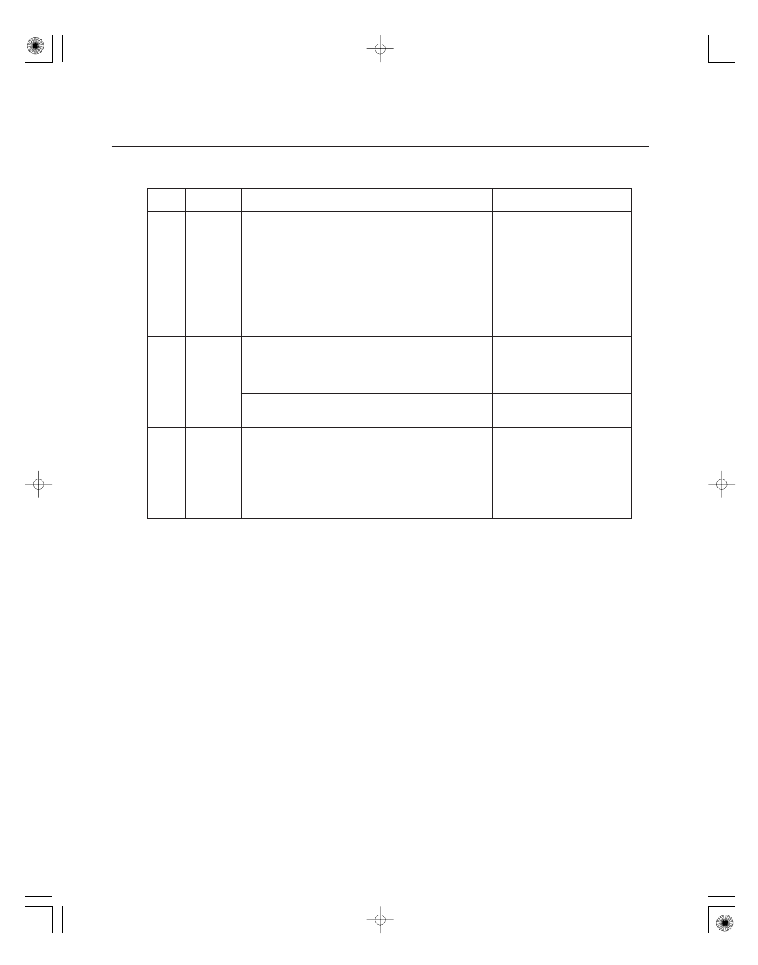
Cavity
Wire
Test condition
Test: Desired result
Possible cause if result is not
obtained
22-120
Multiplex Integrated Control System
MICU Input Test (cont’d)
N22
LT BLU
Under all conditions
Check for continuity between
the N22 terminal and the HVAC
control unit connector (30P)
No. 11 terminal (or climate
control unit) connector (30P)
No. 30 terminal:
There should be continuity.
An open in the wire
HVAC control unit (or
climate control unit)
connector (30P)
disconnected
Check for continuity to ground:
There should be no continuity.
Short to ground
N28
BRN/YEL
Under all conditions
Check for continuity between
the N28 terminal and the gauge
control module connector B
(14P) No. 6 terminal:
There should be continuity.
An open in the wire
Gauge control
module connector B
(14P) disconnected
Check for continuity to ground:
There should be no continuity.
Short to ground
X27
LT GRN
Under all conditions
Check for continuity between
the X27 terminal and the
combination switch connector
(12P) No. 3 terminal:
There should be continuity.
An open in the wire
Combination switch
connector (12P)
disconnected
Check for continuity to ground:
There should be no continuity.
Short to ground