Honda Ridgeline. Manual - part 447
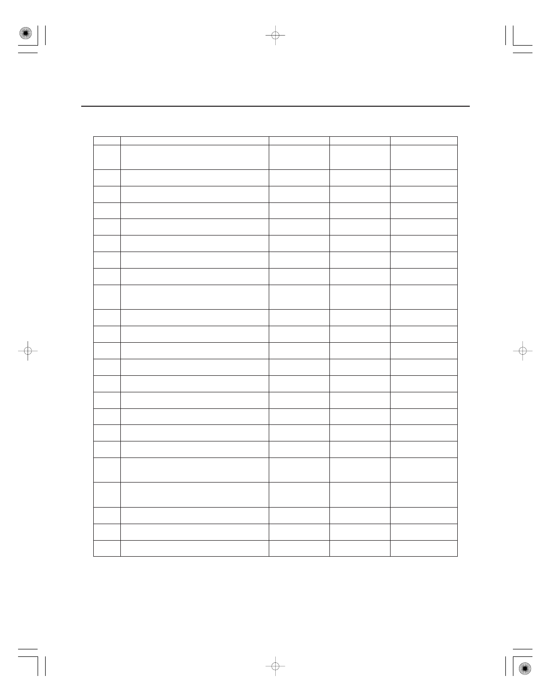
DTC
Description
ECU
DTC type
Page
22-84
Multiplex Integrated Control System
DTC Troubleshooting Index (cont’d)
B1063
Relay Control Module lost communication
with Combination Switch Control Unit
(WIPSW message)
Relay Control
Module
Loss of
Communication
(see page 22-71)
B1075
Headlight switch signal error
Relay Control
Module
Signal Error
(see page 22-168)
B1076
Windshield wiper signal error
Relay Control
Module
Signal Error
(see page 22-228)
B1077
Windshield wiper (As) signal error
Relay Control
Module
Signal Error
(see page 22-230)
B1078
Daytime Running Lights Signal Error
Relay Control
Module
Signal Error
(see page 22-170)
B1080
Power supply circuit (IG1 line) input error for
Relay Control Module and MICU
Relay Control
Module
Battery voltage
(see page 22-114)
B1100
Communication bus line error (BUS-OFF)
Door Multiplex
Control Unit
Loss of
Communication
(see page 22-110)
B1102
Door Multiplex Control Unit internal error
(EEPROM error)
Door Multiplex
Control Unit
Internal Error
(see page 22-115)
B1105
Door Multiplex Control Unit lost
communication with MICU (DOORSW
message)
Door Multiplex
Control Unit
Signal Error
(see page 22-116)
B1106
Door Multiplex Control Unit lost
communication with MICU (MICU message)
Door Multiplex
Control Unit
Signal Error
(see page 22-116)
B1125
Driver’s power window motor A pulse error
Door Multiplex
Control Unit
Signal Error
(see page 22-214)
B1126
Driver’s power window motor B pulse error
Door Multiplex
Control Unit
Signal Error
(see page 22-215)
B1127
Driver’s door lock key cylinder switch LOCK/
UNLOCK signal error
Door Multiplex
Control Unit
Signal Error
(see page 22-134)
B1128
Driver’s door lock switch LOCK/UNLOCK
signal error
Door Multiplex
Control Unit
Signal Error
(see page 22-136)
B1129
Driver’s door lock knob switch LOCK/
UNLOCK signal error
Door Multiplex
Control Unit
Signal Error
(see page 22-137)
B1140
Driver’s power window position detect
circuit error
Door Multiplex
Control Unit
Signal Error
(see page 22-216)
B1150
Communication bus line error (BUS-OFF)
Gauge Control
Module
Loss of
Communication
(see page 22-110)
B1152
Gauge Control Module internal error
(EEPROM error)
Gauge Control
Module
Internal Error
(see page 22-254)
B1155
Gauge Control Module lost communication
with Combination Switch Control Unit
(HLSW message)
Gauge Control
Module
Loss of
Communication
(see page 22-254)
B1156
Gauge Control Module lost communication
with Combination Switch Control Unit
(WIPSW message)
Gauge Control
Module
Loss of
Communication
(see page 22-254)
B1157
Gauge Control Module lost communication
with MICU (MICU message)
Gauge Control
Module
Loss of
Communication
(see page 22-255)
B1158
Gauge Control Module lost communication
with Relay Control Module (RM message)
Gauge Control
Module
Loss of
Communication
(see page 22-255)
B1159
Gauge Control Module lost communication
with MICU (DOORSW message)
Gauge Control
Module
Loss of
Communication
(see page 22-255)