Honda Ridgeline. Manual - part 445


  Index      Honda     Honda Ridgeline - service repair manual 2006-2008 year


Search            


Content   ..  443  444  445  446   ..


Honda Ridgeline. Manual - part 445


03

04

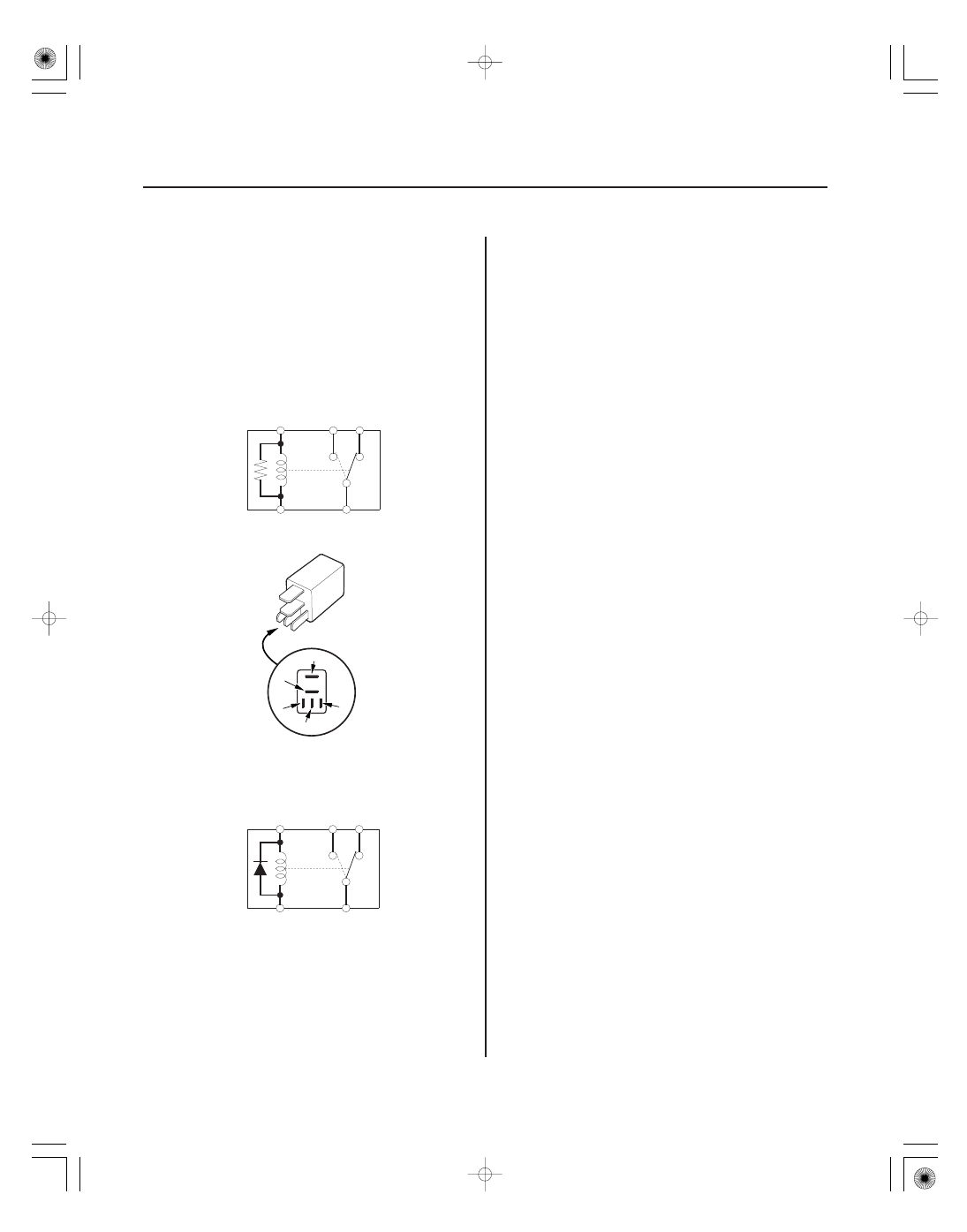
Five-terminal type B

Resistance type

Diode type

22-76

Relays

Power Relay Test (cont’d)

1

5

4

3

2

2

5 ( )

3 ( )

1

4

2

5 ( )

3 ( )

1

4

Check for continuity between the terminals.

• There should be continuity between the No. 1 and

No. 2 terminals when power is connected to the No. 5
terminal and ground the No. 3 terminal.

• There should be continuity between the No. 1 and

No. 4 terminals when power is disconnected.

01

02

SJC8A00J54200034401FEAT00

*01

SJC8A00J54200034401KBAT00

22-77

22-77

Ignition Switch

Test

Replacement

WHT

YEL

WHT/BLK

BLK/WHT

BLK/YEL

A

Terminal

Position

O (LOCK)

I (ACC)

II (ON)

III (START)

WHT/
BLK
(ACC)

WHT
(BAT)

BLK/
YEL
(IG1)

BLK/
WHT
(ST)

YEL
(IG2)

B

A

SRS components are located in the area. Review the
SRS component locations (see page 24-14), and
precautions and procedures (see page 24-16) before
performing repairs or servicing.

1. Make sure you have the anti-theft codes for the

audio system and the navigation system (if
equipped). Make sure the ignition switch is OFF.

2. Disconnect the battery negative cable.

3. Remove the left front door sill trim and left kick

panel (see page 20-60).

4. Disconnect the 6P connector (A) from the under-

dash fuse/relay box.

5. Check for continuity between the terminals in each

switch position according to the table.

6. If the continuity checks do not agree with the table,

replace the ignition switch (see page 22-77).

7. After reconnecting the battery, enter the anti-theft

codes for the audio system and the navigation
system (if equipped). Set the clock (on vehicles
without navigation).

SRS components are located in the area. Review the
SRS component locations (see page 24-14), and
precautions and procedures (see page 24-16) before
performing repairs or servicing.

1. Make sure you have the anti-theft codes for the

audio system and the navigation system (if
equipped). Make sure the ignition switch is OFF.

2. Disconnect the battery negative cable.

3. Remove the left front door sill trim and left kick

panel (see page 20-60).

4. Disconnect the 6P connector (A) from the under-

dash fuse/relay box.

5. Remove the two screws and the ignition switch (B).

6. Install the reverse order of removal.

7. After reconnecting the battery, enter the anti-theft

codes for the audio system and the navigation
system (if equipped). Set the clock (on vehicles
without navigation).

8. Confirm that all system work properly.

9. Do the power window control unit reset procedure

(see page 22-209).

Wire side of
female terminals

*01

SJC8A00J00050600000DAAT10

22-78

Multiplex Integrated Control System

Component Location Index

RELAY CONTROL MODULE
(Built into the under-hood fuse/relay box)

CEILING LIGHT

DOOR MULTIPLEX CONTROL UNIT
(Built into the power window master switch)

MICU
(Built into the under-dash fuse/relay box)

Input Test, page 22-125

Replacement, page 22-195

Input Test, page 22-123

Input Test, page 22-117

*02

22-79

GAUGE CONTROL MODULE

HVAC CONTROL UNIT

CLIMATE CONTROL UNIT

IGNITION KEY LIGHT

COMBINATION SWITCH CONTROL UNIT
(Built into the combination switch)

Self-diagnostic Procedure, page 22-244
Input Test, page 22-122

Troubleshooting,

page 21-8

Troubleshooting,

page 21-83

Test, page 22-204

Input Test, page 22-124


Content   ..  443  444  445  446   ..