Honda Ridgeline. Manual - part 444


  Index      Honda     Honda Ridgeline - service repair manual 2006-2008 year


Search            


Content   ..  442  443  444  445   ..


Honda Ridgeline. Manual - part 444


01

SJC8A00J54226562100KDAT10

Removal

Installation

22-72

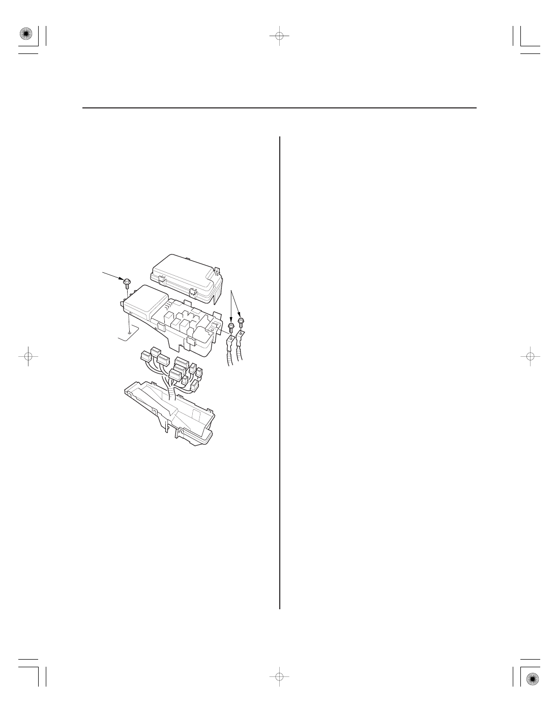
Under-hood Fuse/Relay Box

Removal and Installation

A

B

1. Make sure you have the anti-theft codes for the

audio system and the navigation system (if
equipped). Make sure the ignition switch is OFF.

2. Disconnect the negative battery cable, then

disconnect the positive cable, and wait at least
3 minutes.

3. Remove the screws (A) for the alternator and

battery cable terminals from the under-hood fuse/
relay box.

4. Remove the mounting bolt (B) from the under-hood

fuse/relay box.

5. Remove the bottom cover from the under-hood

fuse/relay box.

6. Disconnect the connectors from the under-hood

fuse/relay box.

7. If replacing the fuse/relay box, carefully remove the

relays by prying under the base of the relay.

NOTE: Do not use pliers. Pliers will damage the
relays, which could cause the engine to stall or not
start.

1. Install the relays and connect the connectors to the

under-hood fuse/relay box, then install the under-
hood fuse/relay box in the reverse order of removal.

2. Install the removed parts in the reverse order of

removal.

3. Connect both the positive and negative cables to

the battery.

4. Do the power window control unit reset procedure

(see page 22-209).

5. Enter the anti-theft codes for the audio and the

navigation system (if equipped). Set the clock (on
vehicles without navigation).

6. Confirm that all systems work properly.

01

SJC8A00J54226562001KDAT00

Removal

Installation

22-73

Under-dash Fuse/Relay Box

Removal and Installation

A

SRS components are located in this area. Review the
SRS component locations (see page 24-14), and
precautions and procedures (see page 24-16) before
performing repairs or service.

1. Make sure you have the anti-theft codes for the

audio system and the navigation system (if
equipped). Make sure the ignition switch is OFF.

2. Disconnect the negative battery cable, then

disconnect the positive cable, and wait at least
3 minutes.

3. Remove the left front door sill trim and left kick

panel (see page 20-60).

4. Disconnect the connectors from the fuse side of

the under-dash fuse/relay box (A).

5. Remove the two mounting bolts and pull the fuse/

relay box away from the body.

6. Disconnect the connectors and remove the under-

dash fuse/relay box.

NOTE: Some SRS harness connectors are spring-
loaded lock type (see page 24-21).

7. If replacing the fuse/relay box, carefully remove the

relays by prying under the base of the relay.

NOTE: Do not use pliers. Pliers will damage the
relays, which could cause the engine to stall or not
start.

1. Install relays and connect the connectors to the

under-dash fuse/relay box, then install the under-
dash fuse/relay box in the reverse order of removal.

2. Install the removed parts in the reverse order of

removal.

3. Connect both the positive cables and negative

cables to the battery.

4. Do the power window control unit reset procedure

(see page 22-209).

5. Enter the anti-theft codes for the audio system and

the navigation system (if equipped). Set the clock
(on vehicles without navigation).

6. Confirm that all systems work properly.

SJC8A00J54200014401FEAT00

22-74

Battery

Battery Test

A battery can explode if you do not follow the
proper procedure, causing serious injury to anyone
nearby. Follow all procedures carefully and keep
sparks and open flames away from the battery.

Use an ED-18

Battery Tester, and follow the

manufacturer’s procedures. If you don’t have one of
these computerized testers, follow this conventional
test procedure:

1. Be sure the temperature of the electrolyte is

between 70 °F (21 °C) and 100 °F (38 °C).

2. Inspect the battery case for cracks or leaks.

• If the case is damaged, replace the battery.
• If the case looks OK, go to step 3.

3. Check the test indicator window.

• If the test indicator window indicates the battery

is charged, go to step 4.

• If the test indicator window indicates a low

charge, go to step 7.

4. Apply a 300 amp load for 15 seconds to remove the

surface charge.

5. Wait 15 seconds, then apply a test load of 280 amps

for 15 seconds.

6. Record battery voltage.

• If voltage is above 9.6 V, the battery is OK.
• If voltage is below 9.6 V, go to step 7.

7. Charge the battery on High (40 amps) until the test

indicator window shows the battery is charged,
plus an additional 30 minutes. If the battery charge
is very low, it may be necessary to bypass the
charger’s polarity protection circuitry.

• If the test indicator window indicates the battery

is charged within three hours, repeat steps 4
through 6. If the battery is still below 9.6 V,
replace the battery.

• If the test indicator window indicates the battery

is not charged within three hours, replace the
battery.

TM

01

02

SJC8A00J54460647111FEAT00

Relay

Test

Resistance type

Diode type

Normally-open type

22-75

Relays

Power Relay Test

3

4

2

1

1

3 ( )

4 ( )

2

2

4 ( )

3 ( )

1

Use this chart to identify the type of relay, then do the
test listed for it.

NOTE: For the turn signal/hazard relay input test
(see page 22-188).

A/C compressor clutch
relay

Normally-open type

A/F sensor relay
Rear accessory power
socket relay
Blower motor relay
A/C condenser fan relay
Ignition coil relay
PGM-FI main relay 1
(FI MAIN), 2 (Fuel pump)
Power window relay
Radiator fan relay
Heated windshield wiper
area relay
Seat heater relay
Low beam cut relay
(Canada)
Cargo area light relay
Front accessory power
socket relay
VTM-4 relay
ETCS relay
Starter cut relay
Trailer lighting connector
relay
Daytime running lights
relay (Canada)

Five-terminal type

Fan control relay
Moonroof close relay
Moonroof open relay

Check for continuity between the terminals.

• There should be continuity between the No. 1 and

No. 2 terminals when power is connected to the No. 4
terminal and ground the No. 3 terminal.

• There should be no continuity between the No. 1 and

No. 2 terminals when power is disconnected.

(cont’d)


Content   ..  442  443  444  445   ..