Honda Ridgeline. Manual - part 327
―――
―――
―――
―――
―――
―――
−
―――
―――
―――
+
−
+
−
+
−
−
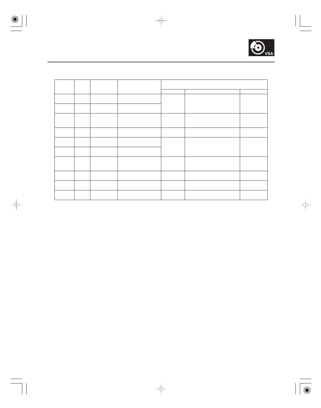
Terminal
number
Wire
color
Terminal
sign
Description
Measurement (Disconnect the VSA
control unit 46P connector)
Terminal
Conditions
Voltage
19-45
26
WHT/
RED
FLP
Sends left-front
wheel speed
28
LT
GRN
FRP
Sends right-front
wheel speed
33
WHT
CAN-H
F-CAN
communication
circuit
40
GRN/
WHT
IG1
Power source for
activating the system
40
GND
Ignition switch ON (II)
Battery
voltage
41
RED
RL-GND
Detect left-rear wheel
sensor signal
42
BLU/
WHT
FL
B
Detect left-front
wheel sensor signal
43
BLK
GND2
Ground for the VSA
modulator-control
unit
43
GND
At all time
0.1 V or less
44
WHT/
RED
B SOL
Power source for the
valve relay
44
GND
At all time
Battery
voltage
45
WHT
B MOT
Power source for the
motor relay
45
GND
At all time
Battery
voltage
46
BLK
GND1
Ground for the pump
motor
46
GND
At all time
0.1 V or less
(cont’d)