Honda Ridgeline. Manual - part 299
01
02
03
SJC8A00B20200056851KBAT00
Special Tools Required
18-21
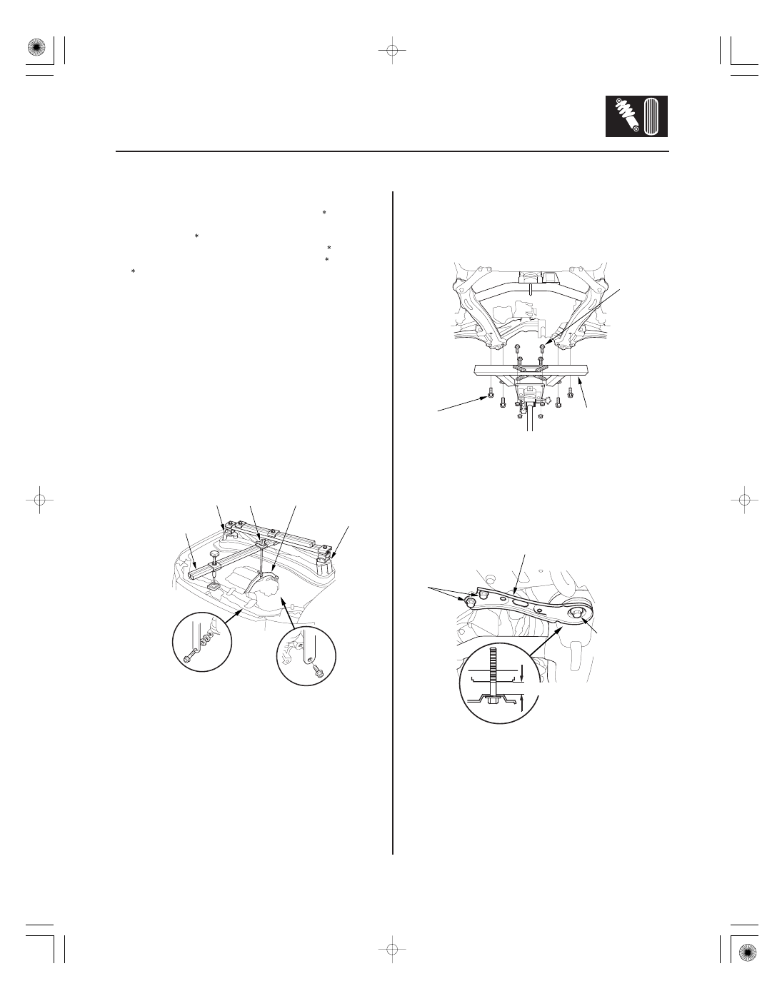
Stabilizer Bar Replacement
A
B
C
VSB02C000024
AAR-T-12566
VSB02C000024
VSB02C000019
C
10 x 1.25 mm
54 N·m
(5.5 kgf·m, 40 lbf·ft)
B
A
EQS02BMDXSB0
A
12 x 1.25 mm
74 N·m
(7.5 kgf·m,
54 lbf·ft)
C
14 x 1.5 mm
103 N·m
(10.5 kgf·m,
75.9 lbf·ft)
14 mm (9/16 in.)
B
• Front subframe adapter EQS02BMDXSB0
• Engine support hanger, A and Reds
AAR-T-12566
• Engine hanger balance bar VSB02C000019
• Engine hanger adapter set VSB02C000024
Available through the American Honda Tool and
Equipment program 1-888-424-6857
1. Raise the front of the vehicle, and support it with
safety stands in the proper locations (see page
1-10).
2. Remove the front wheels.
3. Remove the service caps for the damper flange
nuts, and place the engine support hanger stands
(VSB02C000024) over the flange nuts (see step 55
on page 5-8).
4. Install the engine balancer bar (VSB02C000019);
attach the front arm (A) to the front cylinder head
with the spacer and the 10 mm bolt, and attach the
rear arm (B) to the rear cylinder head with the
8 mm bolt.
5. Install the engine support hanger (AAR-T-12566) to
the vehicle, and attach the hook to the engine
balancer bar slot. Tighten the wing nut (C) by hand,
and lift and support the engine.
6. Disconnect the stabilizer links from the stabilizer
bar on the right and left sides (see page 18-20).
7. Remove the front splash shield (A) (see page
20-179).
8. Line up the slots in the arms with the bolt holes on
the corner of the jack base, then attach the front
subframe adapter (A) to the jack base with the bolts
(B) that came with the jack. Tighten all bolts
securely.
9. Raise the jack to vehicle height, then attach the
front subframe adapter to the front subframe using
the subframe stiffener mounting bolts (C) and bolt
holes.
10. Remove the four 12 mm flange bolts (A) from the
front suspension subframe front brackets (B).
11. Loosen the two 14 mm flange bolts (C) on the front
suspension subframe so they are about 14 mm
(9/16 in.) from the mounting surface. Do not loosen
the 14 mm flange bolts more than necessary.
(cont’d)