Honda Ridgeline. Manual - part 279


  Index      Honda     Honda Ridgeline - service repair manual 2006-2008 year


Search            


Content   ..  277  278  279  280   ..


Honda Ridgeline. Manual - part 279


03

04

05

06

16-42

Driveline/Axle

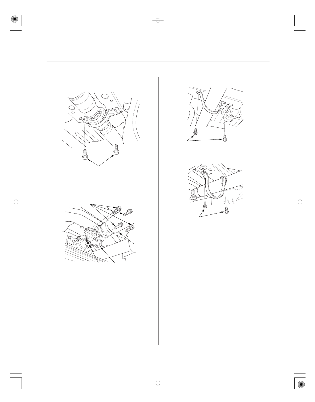
Propeller Shaft Installation (cont’d)

10 x 1.25 mm
39 N·m (4.0 kgf·m, 29 lbf·ft)

10 x 1.25 mm
72 N·m (7.3 kgf·m, 53 lbf·ft)

A

B

C

8 x 1.25 mm
22 N·m (2.2 kgf·m, 16 lbf·ft)

8 x 1.25 mm
22 N·m (2.2 kgf·m, 16 lbf·ft)

5. Install the center support bearing mounting bolts.

Make sure you use new bolts.

6. Install the propeller shaft (A) onto the transfer

companion flange (B) by aligning the reference
mark (C). Make sure you use new mounting bolts.

7. Install the No. 2 propeller shaft protector.

8. Install the No. 1 propeller shaft protector.

9. If you installed a new propeller shaft, test drive the

vehicle at 55 mph (88 kph) and check for noise or
vibration.

• If there is no noise or vibration, the repair is

complete.

• If there is a noise or vibration, go to step 10.

10. Remove the mounting bolts from the propeller

shaft at the rear differential companion flange.
Note the current alignment of the propeller shaft to
rear differential companion flange.

11. Rotate the propeller shaft 180 degrees from its

current alignment with the rear differential
companion flange.

12. Install new mounting bolts and tighten them to the

specified torque.

SJC8A000000000J1702ABAT00

SUPPLEMENTAL RESTRAINT SYSTEM (SRS) (If steering maintenance required)

The Ridgeline SRS includes a driver’s airbag in the steering wheel hub, a passenger’s airbag in the dashboard above
the glove box, seat belt tensioners in the front seat belt retractors, side curtain airbags in the sides of the roof, and side
airbags in the front seat-backs. Information necessary to safely service the SRS is included in this Service Manual.
Items marked with an asterisk (

) on the contents page include or are located near SRS components. Servicing,

disassembling, or replacing these items requires special precautions and tools, and should be done by an authorized
Honda dealer.

• To avoid rendering the SRS inoperative, which could lead to personal injury or death in the event of a severe frontal

or side collision, all SRS service work should be done by an authorized Honda dealer.

• Improper service procedures, including incorrect removal and installation of the SRS, could lead to personal injury

caused by unintentional deployment of the airbags and/or side airbags.

• Do not bump or impact the SRS unit, front impact sensors, or side impact sensors when the ignition switch is ON (II),

or for at least 3 minutes after the ignition switch is turned OFF; otherwise, the system may fail in a collision, or the
airbags may deploy.

• SRS electrical connectors are identified by yellow color coding. Related components are located in the steering

column, front console, dashboard, dashboard lower panel, in the dashboard above the glove box, in the front seats,
in the roof side, and around the floor. Do not use electrical test equipment on these circuits.

SJC8A000000000J1702ZCAT00

Steering

Power Steering

................................................................

........................................

..............................

........................................

......................

.....................................................

................

..........

.............................................

............................................

.......................................................

................................

.....................................................

............................................................

............................................

...............

........................................

..............

.......................................

........................................

..............................................

........................................
........................................

....................................

.........................

.....................

Special Tools

. 17-2

Component Location Index

. 17-3

Symptom Troubleshooting Index

. 17-4

Symptom Troubleshooting

. 17-6

Steering Wheel Rotational Play Check

. 17-7

Power Assist Check

. 17-7

Steering Linkage and Gearbox Inspection

. 17-8

Pump Pressure Test with T/N 07406-0010001

. 17-9

Pump Pressure Test with T/N 07406-001000A

or T/N 07406-001A101

. 17-10

Fluid Leakage Inspection

. 17-11

Fluid Replacement

. 17-12

Power Steering Hose, Line, and

Pressure Switch Replacement

. 17-13

Pump Replacement

. 17-14

Pump Overhaul

. 17-15

Steering Wheel Removal

. 17-21

Steering Wheel Disassembly/Reassembly

. 17-22

Steering Wheel Installation

. 17-23

Steering Column Removal and Installation

. 17-24

Steering Column Inspection

. 17-27

Steering Lock Replacement

. 17-28

Rack Guide Adjustment

. 17-29

Steering Gearbox Removal

. 17-30

Steering Gearbox Overhaul

. 17-37

Steering Gearbox Installation

. 17-52

Tie-rod Ball Joint Boot Replacement

. 17-57

Gearbox Mount Cushion Replacement

. 17-58

01

01

01

01

01

01

01

01

01

01

01

01

01

01

01

01

01

01

SJC8A000000000J1702PAAT00

Ref. No.

Tool Number

Description

Qty

17-2

Power Steering

Special Tools

07GAF-PH70100

Pilot Collar

1

07MAA-SL00100

Locknut Wrench, 40 mm

1

07MAC-SL0A102

Ball Joint Remover, 32 mm

1

07NAG-SR3090A

Valve Seal Ring Sizing Tool

1

07RAK-S040122

P/S Joint Adapter (Hose)

1

07TAF-SZ50100

Cylinder End Seal Remover Attachment

1

07VAK-P8A011A

P/S Joint Adapter (Pump)

1

07VAK-P8A012B

P/S Joint Adapter Plate (Pump)

1

07ZAB-S5A0100

Pulley Holder

1

07ZAG-S3VA100

Piston Seal Ring Guide

1

07ZAG-S3VA200

Piston Seal Ring Sizing Tool

1

07406-0010001, 07406-001000A ,
or 07406-001A101

P/S Pressure Gauge

1

07746-0010100

Attachment, 32 x 35 mm

1

07749-0010000

Driver

1

07946-1870100

Attachment, 28 x 30 mm

1

07965-SA50500

Front Hub Disassembly Tool

1

07974-SA5020A or 07974-SA50200

Sleeve Seal Ring Sizing Tool

1

07974-SA50800

Ball Joint Boot Clip Guide

1


Content   ..  277  278  279  280   ..