Honda Ridgeline. Manual - part 278


  Index      Honda     Honda Ridgeline - service repair manual 2006-2008 year


Search            


Content   ..  276  277  278  279   ..


Honda Ridgeline. Manual - part 278


07

08

16-38

Driveline/Axle

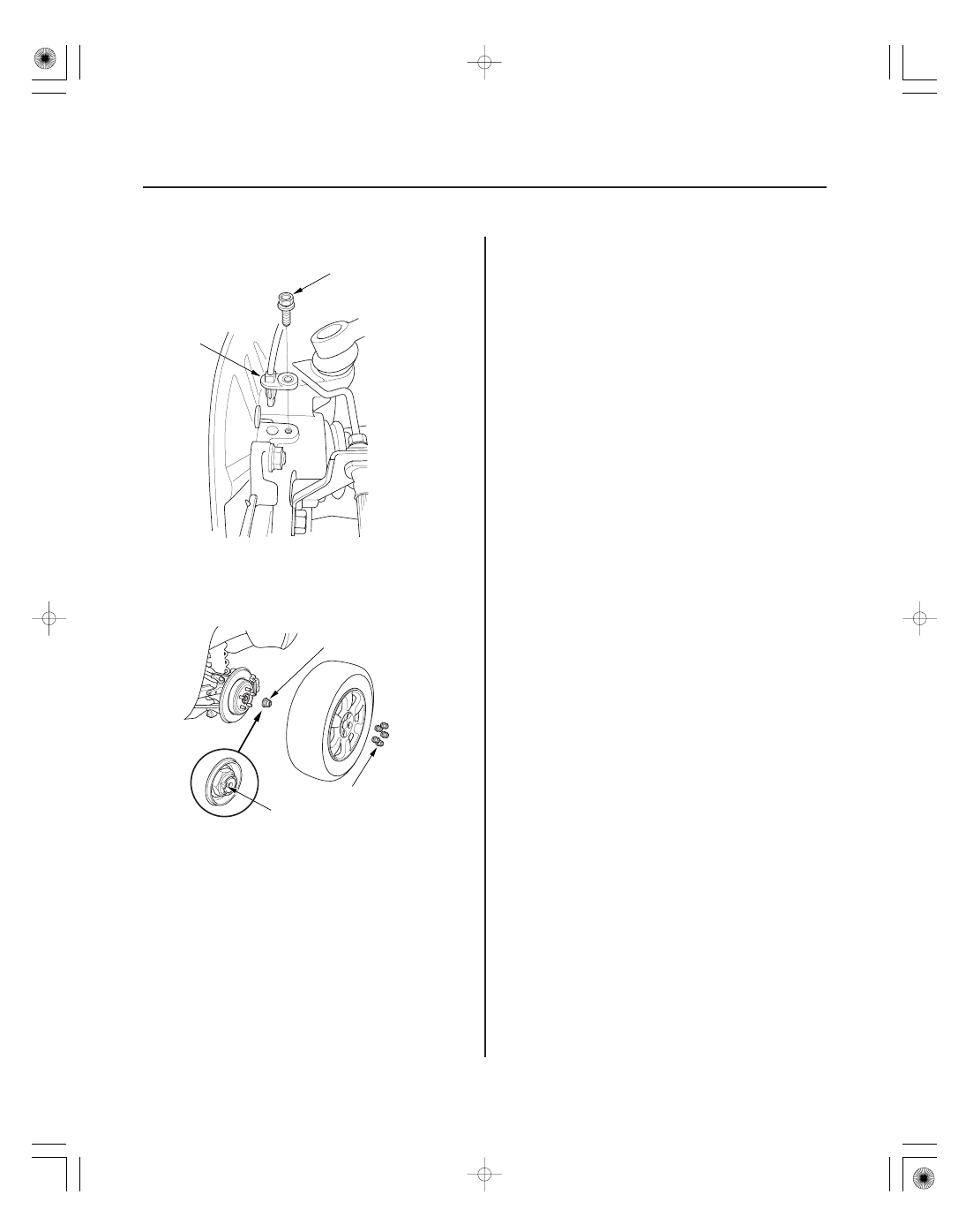
Rear Driveshaft Installation (cont’d)

A

6 x 1.0 mm
9.3 N·m
(0.95 kgf·m, 6.9 lbf·ft)

14 x 1.5 mm
127 N·m
(13.0 kgf·m, 94 lbf·ft)

A
24 x 1.5 mm
245 N·m (25.0 kgf·m, 181 lbf·ft)

B

9. Install the VSA rear wheel sensor (A).

10. Install a new spindle nut (A), then tighten the nut.

After tightening, use a drift to stake the spindle nut
shoulder (B) against the driveshaft.

11. Clean the mating surfaces of the brake disc and the

rear wheel, then install the rear wheel with the
wheel nuts.

12. Turn the rear wheel by hand, and make sure there

is no interference between the driveshaft and
surrounding parts.

13. Refill the differential with recommended fluid

(see page 15-47).

14. Check the rear wheel alignment, and adjust it if

necessary (see page 18-5).

01

02

03

SJC8A00E00000047151MAAT00

Universal Joint and Boots

Propeller Shaft Runout

16-39

Propeller Shaft Inspection

A

No. 1 Propeller Shaft Runout

Service Limit: 1.5 mm (0.06 in.)

No. 2 Propeller Shaft Runout

Service Limit: 1.5 mm (0.06 in.)

1. Shift the transmission to the N position.

2. Raise the vehicle off the ground, and support it with

safety stands in the proper locations (see page
1-10).

3. Check the center support bearing (A) for excessive

play or rattle. If the center support has excessive
play or rattle, replace the propeller shaft assembly.

4. Check the universal joint boots for damage and

deterioration. If the boots are damaged or
deteriorated, replace the propeller shaft assembly.

5. Check the universal joints for excessive play or

rattle. If the universal joints have excessive play or
rattle, replace the propeller shaft assembly.

6. Install a dial indicator with its needle on the center

of No. 1 propeller shaft or No. 2 propeller shaft.

7. Turn the other propeller shaft slowly and check the

runout. Repeat this procedure for the other
propeller shaft.

8. If the runout on either propeller shaft exceeds the

service limit, replace the propeller shaft assembly.

01

02

03

04

SJC8A00E00000047151KAAT00

16-40

Driveline/Axle

Propeller Shaft Removal

A

B

C

1. Raise the vehicle off the ground, and support it with

safety stands in the proper locations (see page
1-10).

2. Remove the No. 1 propeller shaft protector.

3. Remove the No. 2 propeller shaft protector.

4. Make a reference mark (A) across the propeller

shaft (B) and transfer companion flange (C).

5. Separate the propeller shaft from the transfer

assembly.

6. Remove the center support bearing mounting bolts.

05

01

02

SJC8A00E00000047151KCAT00

16-41

16-41

Propeller Shaft Installation

A

B

C

A

B

C

D

E

10 x 1.25 mm
72 N·m (7.3 kgf·m, 53 lbf·ft)

A

B

7. Make a reference mark (A) across the propeller

shaft (B) and rear differential companion flange (C).

8. Separate the propeller shaft from the rear

differential, then remove the propeller shaft.

1. If you are installing a new propeller shaft, go to

step 2.
If you reinstalling the original propeller shaft, go to
step 3.

2. Install the new propeller shaft (A) onto the rear

differential (B), by aligning the reference mark (C)
on the new propeller shaft with the factory
reference mark (D) on the companion flange (E). Do
not use the marks you made on the companion
from the removal procedure. If there are no factory
marks on the companion flange, go to step 4.

3. Reinstall the propeller shaft (A) to the rear

differential (B) by aligning the reference marks (C)
you made during the removal procedure.

4. Attach the propeller shaft to the rear differential

with new mounting bolts. Tighten the bolt to the
specified torque.

(cont’d)


Content   ..  276  277  278  279   ..