Honda Ridgeline. Manual - part 135
*01
*02
SJC8A00A20336300000DAAT00
11-304
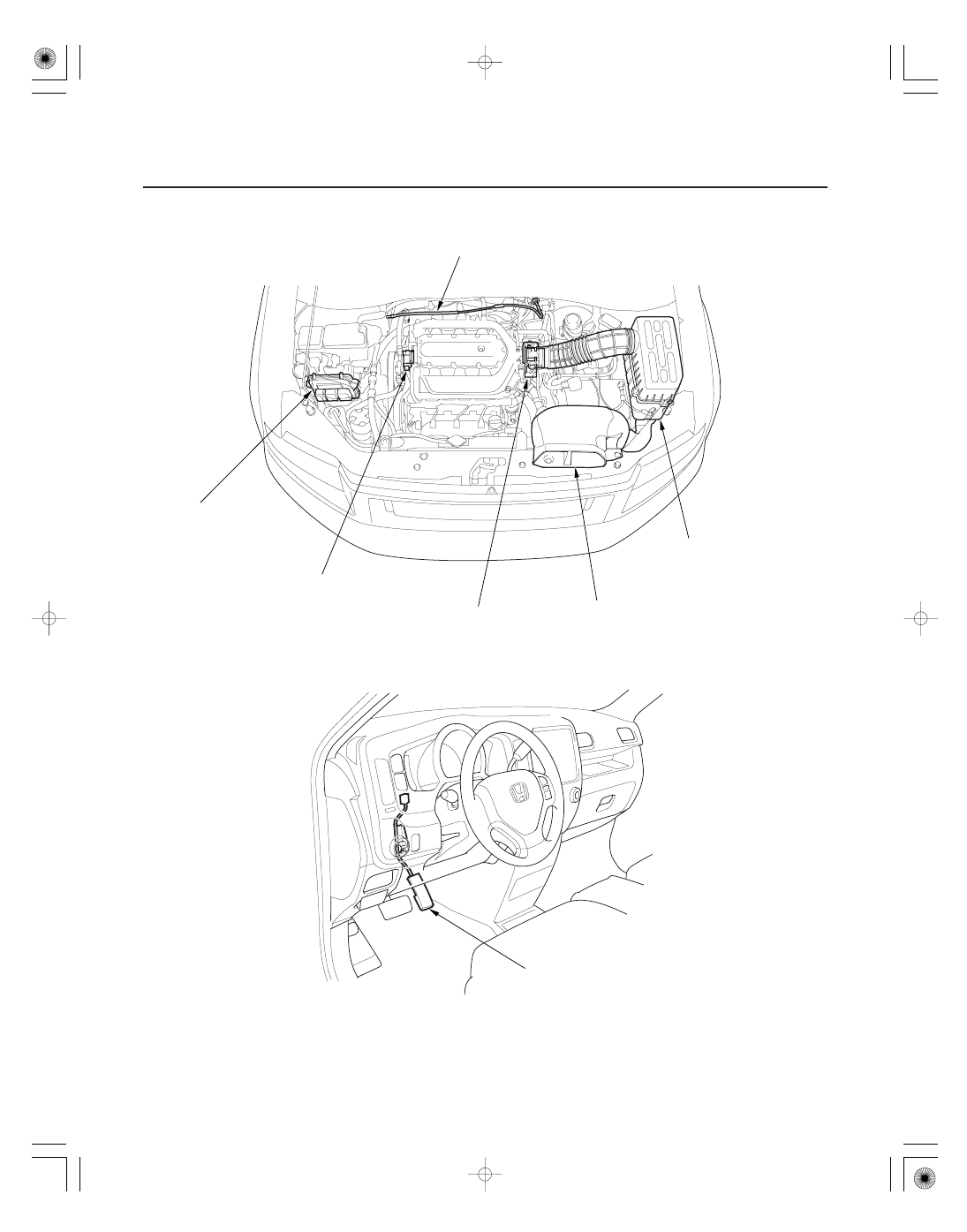
Intake Air System
Component Location Index
POWERTRAIN CONTROL
MODULE (PCM)
THROTTLE BODY
AIR INTAKE DUCT
AIR CLEANER
THROTTLE CABLE
INTAKE MANIFOLD TUNING
(IMT) ACTUATOR
ACCELERATOR PEDAL
Update, page 11-7
Substitution, page 11-8
Replacement, page 11-205
Test, page 11-314
Cleaning, page 11-314
Removal/Installation, page 11-319
Disassembly/Reassembly, page 11-320
Removal/Installation, page 11-316
Removal/Installation,
page 11-315
Element Inspection/Replacement,
page 11-315
Adjustment, page 11-317
Removal/Installation, page 11-317
Replacement, page 11-316
Replacement, page 11-321