Honda Ridgeline. Manual - part 133


  Index      Honda     Honda Ridgeline - service repair manual 2006-2008 year


Search            


Content   ..  131  132  133  134   ..


Honda Ridgeline. Manual - part 133


01

02

03

04

05

Connection with new retainer

Reconnection to existing retainer

Connection to new fuel line

Reconnection to existing retainer

Connection to new fuel line

11-296

Fuel Supply System

Fuel Line/Quick-Connect Fitting Installation (cont’d)

C

B

A

C

B

A

A

B

C

A

B

A

B

C

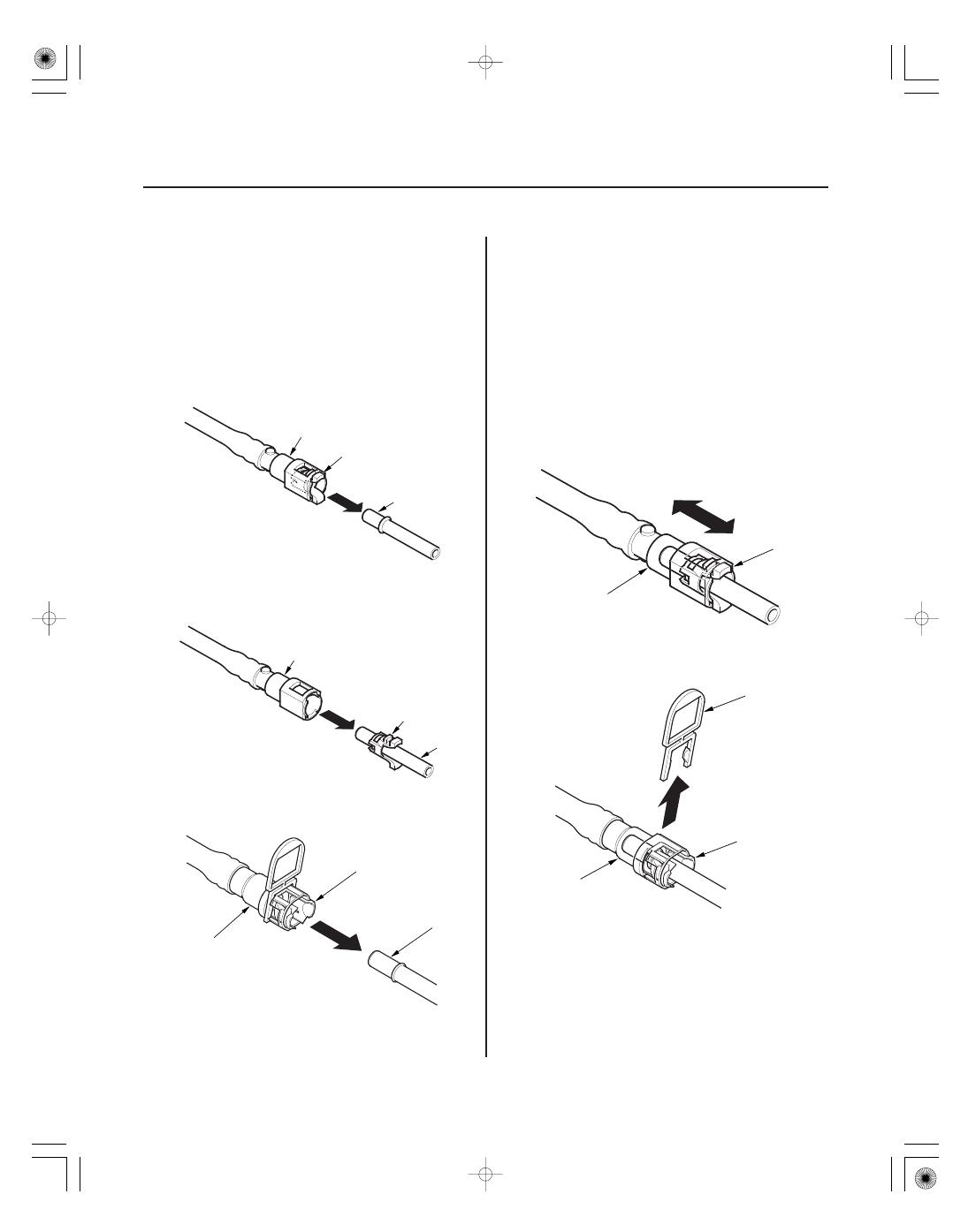
4. Align the quick-connect fittings with the line (A),

and align the retainer locking tabs (B) with the
connector grooves (C). Then press the quick-
connect fittings onto the line until both retainer tabs
lock with a clicking sound.

NOTE: If it is hard to connect, put a small amount of
new engine oil on the line end.

5. When you reconnect the connector with the old

retainer, make sure the connection is secure and
the tabs (A) are firmly locked into place; check
visually and also by pulling the connector (B).
When you replace the fuel line with a new one,
make sure you remove the ring pull (C) upwards
after you confirm the connection is secure.

NOTE: Before you remove the ring pull, make sure
the fuel line connection is secure. If the connection
is not secure, the ring pull could break when you try
to remove it.

6. Reconnect the negative cable to the battery, and

turn the ignition switch ON (II) (but do not operate
the starter motor). The fuel pump will run for about
2 seconds, and fuel pressure will rise. Repeat this
two or three times, and check that there is no
leakage in the fuel supply system.

*01

*02

*03

SJC8A00A20326428521KDAT00

Special Tools Required

Removal

11-297

Fuel Tank Unit Removal and Installation

A

B

C

07AAA-S0XA100

A

A

B

C

Fuel sender wrench 07AAA-S0XA100

1. Relieve the fuel pressure (see page 11-286).

2. Remove the fuel fill cap.

3. Remove the rear seat-back (see page 20-119).

4. Remove the access panel (A) from the floor, then

disconnect the fuel tank unit 5P connector (B).

5. Disconnect the quick-connect fitting (C) from the

fuel tank unit.

6. Using the special tool, loosen the fuel tank unit

locknut (A).

7. Remove the locknut (A), locknut plate (B), and the

fuel tank unit (C).

(cont’d)

*04

*05

*06

Installation

11-298

Fuel Supply System

Fuel Tank Unit Removal and Installation (cont’d)

A

B

A

B

A

B

07AAA-S0XA100

A
93 N·m
(9.5 kgf·m, 69 lbf·ft)

1.

Temporarily attach a new base gasket (A) to the

NOTE:

• Be careful not to damage the new base gasket.
• Be careful not to bend the fuel gauge sending

unit.

• Do not coat the base gasket with oil.

2.

3. Align the marks (B) on the fuel tank and the fuel

tank unit, then insert the fuel tank unit into the fuel
tank until it sits on the base gasket.

NOTE: To avoid a fuel leak, check the base gasket,
visually or by hand, to make sure it is not pinched.

4.

with a new locknut plate (B).

NOTE:

• After tightening, make sure the marks are still

aligned.

• After installation, check the base gasket, visually

or by hand, to be sure it is not pinched.

5. Connect the fuel tank unit 5P connector, then

connect the quick-connect fitting.

6. Reconnect the negative cable to the battery, and

turn the ignition switch ON (II) (but do not operate
the starter motor). The fuel pump will run for about
2 seconds, and fuel pressure will rise. Repeat this
two or three times, then check that there is no
leakage in the fuel supply system.

7. Install the access panel.

8. Install the rear seat-back (see page 20-119).

9. Install the fuel fill cap.

fuel tank unit (B), then insert the fuel tank unit
partially into the fuel tank.

onto the fuel tank.

Transfer the base gasket (A) from the fuel tank unit

Using the special tool, tighten the new locknut (A)

01

SJC8A00A20326428201KBAT00

01

SJC8A00A20326427601KBAT00

11-299

11-299

Fuel Pressure Regulator
Replacement

Fuel Filter Replacement

A

B

C

D

D

A

B

C

D

D

D

1. Remove the fuel tank unit (see page 11-297).

2. Remove the bracket (A).

3. Remove the clip (B).

4. Remove the fuel pressure regulator (C).

5. Install the parts in the reverse order of removal

with new O-rings (D).

NOTE: Coat the O-rings with clean engine oil. Do
not use any other type of oil or fluid.
Do not pinch the O-rings during installation.

The fuel filter should be replaced whenever the fuel
pressure drops below the specified value (see page
11-288), after making sure that the fuel pump and the
fuel pressure regulator are OK.

1. Remove the fuel tank unit (see page 11-297).

2. Remove the fuel filter set (A).

3. Check these items before installing the fuel tank

unit:

• When connecting the wire harness, make sure

the connection is secure and the connectors (B)
are firmly locked into place.

• When installing the fuel gauge sending unit (C),

make sure the connection is secure and the
connector is firmly locked into place. Be careful
not to bend or twist it excessively.

4. Install the parts in the reverse order of removal

with new O-rings (D). When installing the fuel tank
unit, align the marks on the unit and the fuel tank
(see page 11-298).

NOTE: Coat the O-rings with clean engine oil.


Content   ..  131  132  133  134   ..